info@synthe-corp.com

+86-155-3785-7393

Engineered continuous production route

Continuous Vacuum Brazing Furnace

A configurable production-line furnace for repeatable brazing of stable part families. The system is defined around saleable output, takt, joint and filler requirements, conveyor loading, thermal zones, vacuum or protective-gas boundaries, automation and acceptance criteria.

SYNHTE continuous vacuum brazing furnace for automated production
Continuous production platformLine architecture follows takt and process window
Production modelStable part family, repeatable flow and defined changeover policy.
Process envelopeMaterial, filler, joint, cleanliness and thermal-window inputs.
Line integrationLoading, conveying, controls, upstream/downstream handshakes.
Acceptance planTemperature, vacuum or gas, takt, traceability and documentation.

01 / Route boundary

Is continuous brazing the right production model?

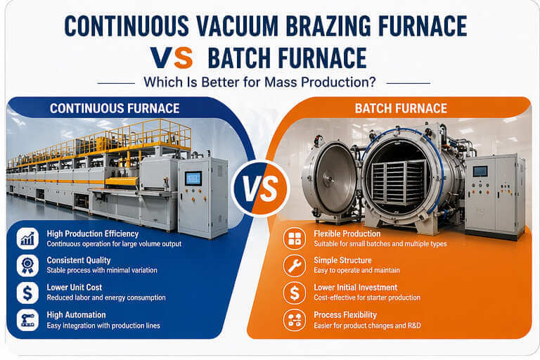
A continuous line earns its place when the process and production system are stable enough to benefit from repeatable flow. It should not be selected only because annual volume appears high.

Strong continuous-line fit

Prioritize flow, repeatability and integration

  • One product family or a controlled group of similar assemblies.
  • Demand can be translated into a stable hourly good-part target.
  • Joint design, filler placement and cleaning are repeatable.
  • Carrier loading and part orientation can be standardized.
  • Upstream and downstream processes can support the required takt.
  • Quality records and line interlocks are defined before quotation.
Review a batch route first

Prioritize flexibility when the production mix moves

  • Many unrelated assemblies require frequent recipe and fixture changes.
  • Demand is intermittent, seasonal or not yet qualified.
  • Long holds, large load variation or development cycles dominate.
  • The process requires load-by-load inspection or exceptional handling.
  • Available floor space, utilities or staffing do not support a line.
  • The validated thermal cycle has not yet been established.

Selection boundary: Choose this route for stable continuous production. For flexible mixed-product or load-by-load processing, review the Vacuum Brazing Furnace selection hub.

02 / Throughput definition

Convert demand into engineering inputs

Line capacity is not a catalogue number. It is calculated from the good-part target, available production time, load density, validated thermal exposure, planned yield, buffers and changeovers.

INPUT 01

Good-part demand

Annual and hourly saleable output by product family, including planned ramp-up and peak demand.

INPUT 02

Operating calendar

Shifts, planned uptime, maintenance windows and the realistic hours available to the brazing line.

INPUT 03

Carrier loading

Parts per carrier, fixture mass, orientation, spacing and repeatable loading or unloading method.

INPUT 04

Thermal residence

Ramp, equalization, brazing window and controlled-cooling time from the approved process route.

INPUT 05

Yield and rework

Target first-pass yield plus the agreed treatment of leak-test, visual or dimensional rejects.

INPUT 06

Changeover policy

Product-family sequence, recipe changes, fixture changes, purge requirements and cleaning intervals.

Required gross input rate = target good parts ÷ available run time ÷ planned first-pass yield

This is only the starting point. The validated thermal residence and carrier pitch then determine conveyor speed, active zone length, buffering and practical line output.

03 / Brazing route

Define the assembly before configuring the furnace

The furnace supports a controlled joining process; it does not replace joint, filler or cleaning development. These six input groups prevent a high-output line from reproducing an unstable process.

MATERIAL

Base alloys and mass

Provide alloy grades, section thicknesses, total part mass and the most temperature-sensitive component.

JOINT

Fit-up and geometry

Share drawings, joint type, target clearance, contact area, distortion risk and fixture constraints.

FILLER

Brazing alloy and placement

Identify filler grade, form, application method, quantity control and any flux or binder restrictions.

CLEANLINESS

Preparation and storage

Define degreasing, oxide control, drying, permitted handling time and contamination limits before loading.

THERMAL WINDOW

Validated cycle limits

Specify ramp, soak, brazing and cooling windows plus thermocouple locations used during qualification.

ACCEPTANCE

Joint quality evidence

Set visual, leak, strength, dimensional or metallographic checks and the sampling plan for production.

04 / Production-line architecture

Build each zone around residence time and isolation

A project may combine or separate these functions. Locks, vestibules, preheat and cooling arrangements are selected from the material route, pressure boundary, takt and plant interface—not assumed as universal standard equipment.

01

Load & identify

Orient the assembly, verify carrier and associate the correct recipe or lot.

02

Isolate

Control transfer between the factory environment and the process atmosphere.

03

Preheat

Manage ramp rate, temperature gradients and volatile-load considerations.

04

Braze

Hold the qualified joint and filler window with defined thermal evidence.

05

Cool

Protect joint quality and part geometry through the selected cooling path.

06

Exit & buffer

Return to safe handling conditions and coordinate downstream flow.

Candidate sequence shown for engineering discussion. The quoted system may use a different number of zones or isolation stages after process review.

05 / Conveying and loading

The handling system is part of the thermal process

Carrier pitch, fixture mass, part orientation and transfer stability affect residence time, temperature response, contamination risk and maintainability.

01

Carrier and fixture

Define hot mass, dimensional stability, repeat-use life and material compatibility with the joining process.

02

Indexing and speed

Match carrier spacing and line movement to the validated exposure time and upstream/downstream cycle.

03

Loading and unloading

Specify manual, assisted or automatic interfaces, orientation checks and rejected-part handling.

04

Service access

Plan cleaning, wear-part replacement, recovery from a stopped carrier and safe maintenance isolation.

05

Contamination control

Define acceptable lubricants, fixture residues, particles and exposure between cleaning and furnace entry.

06 / Process atmosphere

Specify where vacuum ends and controlled gas begins

A continuous system can use high-vacuum process sections, controlled protective-gas sections, or an engineered combination. The pressure architecture must be explicit; “full-line high vacuum” should never be assumed from the product name alone.

High-vacuum process route

Evaluate this route where the alloy, filler and joint-quality target require a defined low-pressure environment during the critical thermal stage.

Engineering inputs
Required pressure at temperature, allowable contamination, outgassing load and pressure-recovery time.
Line implications
Isolation stages, seals, pumping architecture, transfer design and leak-rate acceptance.
Acceptance evidence
Pressure curve, ultimate-vacuum test, pressure-rise test and loaded-cycle behavior.

Controlled protective-gas route

Available gas options include nitrogen or argon. Gas selection and where it is applied depend on alloy compatibility, filler route and the required process boundary.

Engineering inputs
Gas type, purity, dew point or oxygen limit, flow, pressure and consumption target.
Line implications
Purge sequence, isolation, exhaust, gas monitoring and factory safety interfaces.
Acceptance evidence
Gas-quality records, purge response, alarm checks and product-quality results.

07 / Controls and factory interface

Define automation by decisions and records

PLC and touchscreen control are available platform features. Traceability, data exchange and upstream/downstream integration should be written into the RFQ as required interfaces so they are engineered and tested—not treated as implied.

Recipe control

Set access levels, approved parameters, change history and product-to-recipe verification.

Alarms and interlocks

Define line-stop logic, vacuum or gas deviations, conveyor faults and safe recovery states.

Process records

Specify tags, sampling interval, batch or carrier identity, retention period and export format.

Line handshakes

Document signals, network protocol, permissives, buffer status and responsibility at each interface.

08 / Configuration matrix

Translate process inputs into a quotable system

Use this matrix to keep the equipment proposal tied to the product, takt and acceptance plan. Missing values should be marked for joint engineering review rather than replaced with assumptions.

On a narrow screen, swipe horizontally to review all columns.

Continuous vacuum brazing furnace configuration decision matrix
Decision areaSubmit with RFQEngineering impactProposal output
Thermal platformMaterials, filler, brazing window, load mass and ramp limits.Heating element, insulation, zone length, power and cooling route.Temperature platform, zone layout and cycle basis.
Effective work zoneMaximum part/fixture envelope, carrier pitch, weight and orientation.Line opening, chamber dimensions, thermal mass and handling load.Quoted W × H × L and permissible carrier load.
Line rateGood parts/hour, parts/carrier, uptime, yield and changeovers.Conveyor speed, residence length, buffer and production balance.Capacity basis and defined operating assumptions.
Vacuum / gasPressure at process, gas type/purity, outgassing and isolation limits.Pump group, locks, seals, purge/exhaust and monitoring.Pressure architecture, utilities and acceptance tests.
ConveyingLoading concept, fixture material, orientation, upstream/downstream height.Carrier design, drive, indexing, recovery and service access.Material-flow layout and interface definition.
ControlsRecipe, traceability, records, protocols, alarms and user roles.PLC/HMI scope, sensors, network, data storage and handshakes.I/O list, functional description and test cases.
AcceptanceTemperature, pressure, takt, yield, joint tests and documents.Instrumentation, test loads, sampling and demonstration plan.FAT/SAT protocol with agreed pass criteria.

Configurable platform envelope

Available platform data

Use these values to shortlist the temperature platform, vacuum system, work zone, cooling route and line interfaces before quotation.

Maximum operating temperature750°C or 1300°C
Temperature uniformity±3°C
Temperature control accuracy±1°C
Ultimate vacuum6 × 10−4 Pa
Pressure-rise rate0.3 Pa/h
Gas-cooling pressure2 bar
Effective work zone (W × H × L)500 × 500 × 1600 to 500 × 1600 × 3000 mm
Heating-element optionsNi-Cr, molybdenum or graphite
Available system optionsDiffusion-pump or molecular-pump vacuum systems; N₂ or Ar process gas; water or gas cooling

Configuration note: Final configuration is confirmed against the material, workpiece dimensions, takt, process environment and acceptance requirements.

09 / FAT and SAT

Write the acceptance plan before the line is built

The contract or technical agreement should define the test method, instruments, load, sampling period and pass criteria. Standards apply only when they are explicitly agreed for the project.

FAT

Factory Acceptance Test

  • Configuration, utilities, safety devices and document review.
  • Temperature-control and agreed uniformity demonstration.
  • Vacuum, pressure-rise or protective-gas tests as applicable.
  • Conveyor motion, carrier tracking, stops and recovery logic.
  • Recipe, alarm, interlock, data and communication checks.
  • Defined dry run or process demonstration and takt evidence.
SAT

Site Acceptance Test

  • Installed utilities, exhaust, gases and factory safety interfaces.
  • Upstream/downstream handshakes and production-line operation.
  • Loaded cycle with agreed product, fixture and quality checks.
  • Operator, maintenance and fault-recovery training.
  • Site records, spares, manuals and open-item closure.
  • Final acceptance against the signed protocol—not a generic claim.
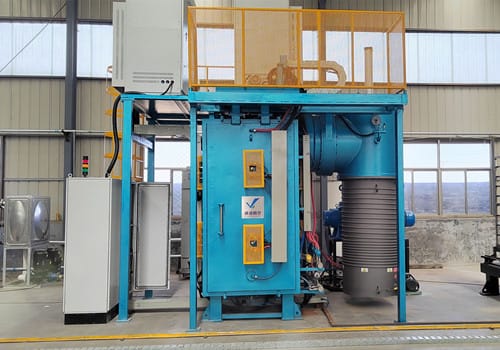
Vacuum furnaces in the SYNHTE production workshop
Workshop evidence supports the manufacturing route; project-specific drawings, tests and delivery scope remain part of the proposal.

10 / Engineering delivery

Control interfaces before fabrication

A continuous line has more boundary conditions than a stand-alone furnace. Mechanical, utility, software, product and acceptance responsibilities should be frozen through staged review.

01

Process and concept reviewConfirm brazing route, takt basis, line boundary, layout and risks.

02

Interface and design reviewFreeze utilities, handling, I/O, safety, data and acceptance methods.

03

Manufacture and integrationFabricate, assemble and test to the approved technical documents.

04

FAT, installation and SATDemonstrate the agreed tests, close deviations and complete handover.

11 / RFQ input package

Send enough data to size the line correctly

Drawings, process evidence and production assumptions are more useful than a model-number request. Unknown items can be marked “to be confirmed” and reviewed jointly.

RFQ 01Materials and filler

Base-alloy grades, filler grade/form, binder or flux constraints.

RFQ 02Part and joint drawings

Envelope, mass, joint geometry, clearance and critical tolerances.

RFQ 03Production target

Good parts/hour, annual demand, shifts, uptime and ramp-up plan.

RFQ 04Loading concept

Parts/carrier, orientation, fixture material, mass and transfer height.

RFQ 05Thermal cycle

Ramp, equalization, brazing and cooling windows with evidence.

RFQ 06Vacuum or gas limits

Pressure at process, gas purity, dew point/oxygen or leak constraints.

RFQ 07Cleaning route

Pre-cleaning, dry storage, allowable exposure and contamination limits.

RFQ 08Changeovers

Product families, frequency, recipe and fixture changes, purge needs.

RFQ 09Factory interfaces

Layout, utilities, exhaust, network and upstream/downstream equipment.

RFQ 10Automation scope

Loading, recipe control, traceability, protocol and data retention.

RFQ 11Quality checks

Visual, leak, strength, dimensional or metallographic requirements.

RFQ 12FAT and SAT

Test loads, pass criteria, documents, training and handover scope.

Ready to define a continuous brazing line?

Send the assembly drawing, filler route, required good-part rate, carrier concept, thermal window and acceptance requirements. The quotation can then separate confirmed scope from items requiring process validation.

Start an engineering review
Technical download

Continuous Vacuum Brazing Furnace Configuration Guide

Download the current reference document or compare all available SYNHTE technical resources.

Contact Us

15+ Years Industrial Experience

Annual output 200+

CE & ISO Certified

Reply within 12 hours

Professional technical support

Free consultation service

Relevant knowledge

Learn how our vacuum furnaces can assist your industry.