info@synthe-corp.com

+86-155-3785-7393

Post-quench heat treatment

Vacuum Tempering Furnace

Configure bright tempering and stress-relief cycles around the material, target properties, working temperature, load geometry, vacuum package, cooling method and acceptance plan.

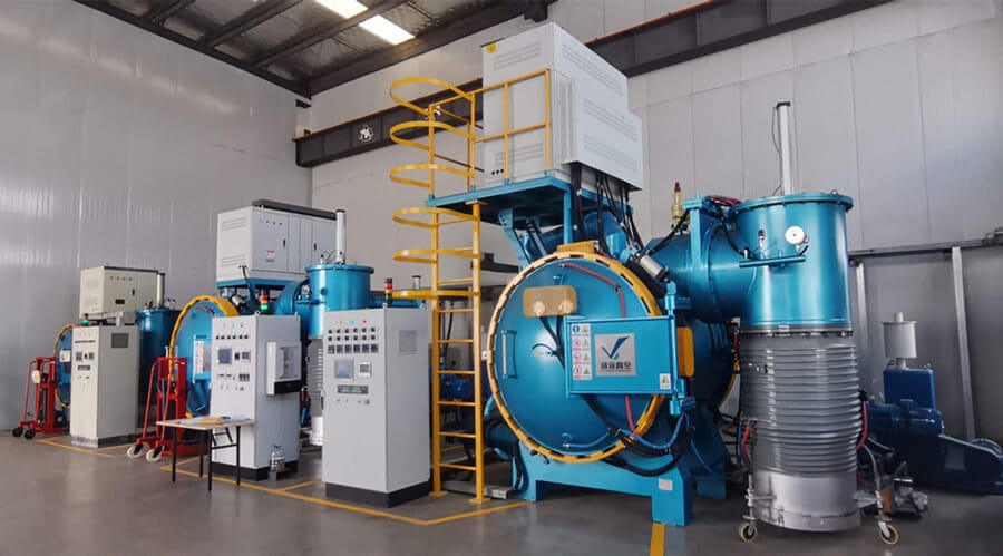
Horizontal vacuum tempering furnace with control cabinet and vacuum pumping system
Horizontal VTH configuration shown with control, vacuum and water-cooled vessel systems.
700°CNi-Cr heating package reference maximum
1100°CMolybdenum heating package reference maximum
2 vacuum routesTwo-stage or three-stage pumping packages
2 loading layoutsHorizontal or vertical, selected by part geometry

Application fit

Select by hardened condition and target result

Vacuum tempering reheats hardened or previously heat-treated loads under vacuum or protective gas to establish the required hardness, toughness, stress and surface condition.

Discuss material and cycle
  • Tool steels

    Balance hardness, toughness and residual stress

    Define the grade, hardening route, incoming hardness, tempering setpoint, soak logic and required final hardness before selecting the furnace package.

  • High-speed and mould steels

    Plan repeat cycles and load consistency

    Multiple tempering cycles, fixture mass and part section thickness determine recovery time, temperature uniformity and production throughput.

  • Alloy steels

    Protect the post-quench surface condition

    Vacuum level, cleanliness, partial-pressure gas and cooling sequence are selected together when bright surface retention and controlled oxidation are project requirements.

  • Special materials

    Material compatibility governs configuration

    Titanium alloys, magnetic materials, electrical iron and copper-alloy projects require material-specific evaluation of temperature, atmosphere, contamination sensitivity and acceptance criteria.

  • Slender parts

    Loading direction supports distortion control

    For tubular, long or thin-wall components, a vertical top- or bottom-loading arrangement can support a more suitable fixture and deformation-control strategy.

Five-step selection route

Turn the tempering cycle into an equipment specification

Furnace size follows the process window and production load rather than chamber dimensions alone.

01

Material state

Grade, hardening process, incoming hardness, surface condition and contamination sensitivity.

02

Target result

Final hardness range, stress-relief objective, dimensional tolerance and visible surface criteria.

03

Thermal cycle

Setpoint, ramp, soak, number of cycles, recovery requirement and load thermocouple plan.

04

Load and cooling

Part envelope, batch mass, fixture mass, orientation, gas pressure and unload temperature.

05

Acceptance

Uniformity, vacuum performance, data records, alarms, utilities and sample-part qualification.

System definition

Match the heating, vacuum and loading architecture

  • Heating package

    Ni-Cr and molybdenum configurations cover different temperature envelopes. Select from the required setpoint, margin, atmosphere and hot-zone life strategy.

  • Heat transfer

    For lower-temperature, high-mass loads, an engineered convection option can improve heating rate and temperature distribution. Fan, gas and cleanliness form one coordinated package.

  • Vacuum system

    Rotary-plus-Roots and rotary-plus-Roots-plus-diffusion-pump routes serve different base-pressure requirements. Specify the required pressure at a stated chamber and degassing condition.

  • Loading layout

    Horizontal loading supports common batch handling; vertical loading can better suit long, tubular or thin-wall parts where fixture direction is central to distortion control.

  • Cooling route

    Define gas type, pressure, fan operation, load density, target unload temperature and permitted cooling time instead of specifying pressure alone.

  • Vessel and utilities

    A double-wall water-cooled vessel requires confirmed water flow, inlet temperature, pressure, quality and interlocks as part of the installation interface.

Open vacuum tempering furnace showing the heating chamber and work basket
Heating chamber and work basket access. Usable-zone selection includes the complete fixture envelope and load spacing.

Configuration matched to the actual load

Part drawings, fixture mass, operating temperature, vacuum level and cooling target establish the heating and pump package.

Request furnace configuration

Reference configuration envelope

VTH reference configurations for furnace selection

The VTH platform covers common post-quench tempering loads with heating, vacuum and cooling packages selected for the specified process window.

Usable-zone examples
300 × 300 × 500 to 800 × 800 × 1200 mm
Width × height × depth reference range; other dimensions are available.
Reference load range
100–1000 kg
Final capacity depends on part and fixture geometry, material and thermal-cycle performance.
Ni-Cr package
Up to 700°C
For suitable tempering and stress-relief temperature windows.
Molybdenum package
Up to 1100°C
Selected where the required operating envelope exceeds the Ni-Cr route.
Vacuum package options
Better than 4 × 10⁻¹ Pa or 4 × 10⁻³ Pa
Defined by pump train under agreed empty, clean, dry and degassed conditions.
Gas cooling reference
2 bar
Cooling result is qualified with gas, fan, load and temperature conditions stated.

Final usable zone, load, heating power, vacuum level, temperature uniformity and cycle performance are documented for the specified part, fixture, utilities and acceptance conditions.

Receive a VTH configuration data sheet aligned with the working zone, load and required process temperature.

Request configuration data

Control and traceability

Control architecture for repeatable tempering cycles

Recipe execution, batch records and protective interlocks operate as one coordinated system from heat-up through controlled cooling.

Operator checking the control system of a VTH vacuum tempering furnace
Internal electrical cabinet layout for a VTH vacuum tempering furnace
VTH furnace controls shown with the operator station and internal electrical cabinet arrangement.
  1. 01
    Cycle executionRamp, soak, pressure, gas and cooling steps run through controlled recipes and user permissions.
  2. 02
    Traceable recordsTime, temperature, vacuum, alarms and batch identifiers support production and quality review.
  3. 03
    Interlocked protectionDoor, vacuum, heating, cooling water, gas and overtemperature permissives protect the process and equipment.
  4. 04
    Defined fault responsePower, water, gas, pump and sensor faults trigger specified safe states and recovery procedures.

Control language, batch data, user access and plant interface are configured for the project.

Configure control system

Acceptance planning

Tie each purchase requirement to a verification method

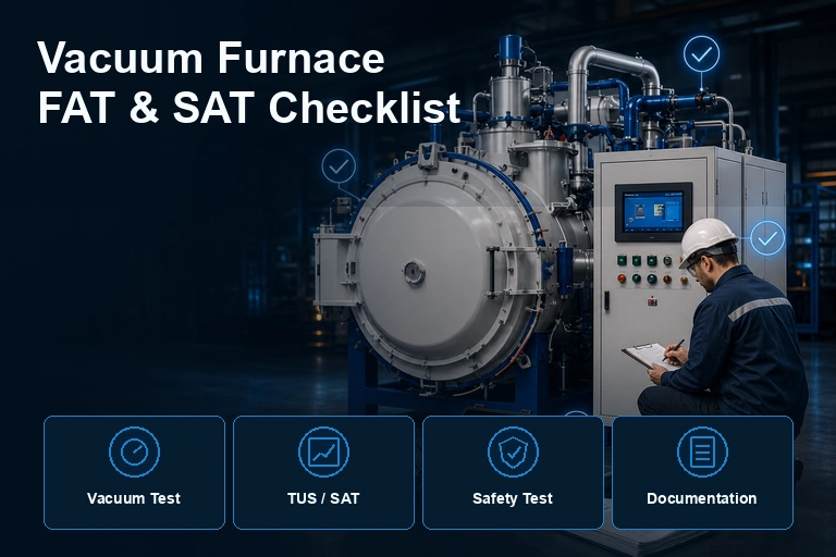
FAT/SAT acceptance links every critical requirement to a defined condition, instrument, load state, record and acceptance limit.

Swipe horizontally to review all acceptance columns.

Recommended vacuum tempering furnace acceptance matrix
Acceptance areaDefine before orderVerify withRecord in
Thermal performanceSetpoints, usable zone, uniformity limit, empty or loaded condition and sensor layout.Calibrated survey instruments and an agreed test method.Temperature survey report and calibration records.
Vacuum performanceTarget pressure, pump train, chamber condition, evacuation time and pressure-rise test method.Blank, clean, dry and degassed chamber test under stated utilities.Pump-down curve, pressure-rise result and instrument status.
Load outcomeReference parts, fixture, cycle, hardness, dimensions and visible surface criteria.Witness load or agreed customer sample with controlled incoming condition.Batch curve, inspection result and deviation log.
CoolingGas, pressure, load, fan logic, target unload temperature and maximum time.Instrumented representative load where cycle time is contractual.Cooling curve and utility conditions.
Safety and controlsPermissives, alarms, emergency states, access levels, recipes and data export.Cause-and-effect checks and simulated fault conditions.FAT checklist, alarm list and operator handover.

Hardness, microstructure, dimensional change and appearance depend on the material, incoming state, recipe, loading and handling. Agreed samples and inspection methods establish these acceptance results.

FAT/SAT scope can include thermal survey, vacuum performance, witness loads, cooling curves, interlock checks and production records.

Define FAT/SAT scope

RFQ checklist

RFQ data for an application-matched furnace

These six data groups align chamber size, heating package, pumps, cooling, loading and acceptance scope with the production requirement.

Submit your tempering requirement
  • 01 · MaterialGrade, part drawing or envelope, incoming heat-treatment state and contamination restrictions.
  • 02 · ResultFinal hardness or stress-relief objective, surface criteria, distortion tolerance and inspection method.
  • 03 · CycleMaximum setpoint, ramp, soak, repeat tempering, cooling target and required cycle time.
  • 04 · LoadNet part mass, fixture mass, quantity per batch, orientation and planned batches per day.
  • 05 · SitePower supply, cooling water, process gas, compressed air, floor space and installation constraints.
  • 06 · AcceptanceFAT/SAT scope, survey standard, vacuum test, sample load, documents, language and data interface.

Specification questions

Clarify the process boundary early

These answers guide initial selection; the project data sheet remains the controlled equipment definition.

Is vacuum tempering the same as vacuum annealing?
No. Tempering normally follows hardening and adjusts hardness, toughness and residual stress. Annealing serves a different metallurgical objective such as softening or broader material conditioning. The required cycle and result determine the applicable furnace route.
How are Ni-Cr and molybdenum heating selected?
Ni-Cr is the reference route up to 700°C, while molybdenum extends the reference temperature envelope to 1100°C. Selection combines operating setpoint, temperature margin, atmosphere, cleanliness and hot-zone life requirements.
When is a vertical furnace worth considering?
Long, tubular and thin-wall parts can benefit from vertical loading when gravity, fixture direction and handling make it easier to control deformation. Part drawings, load height and lifting requirements are needed to verify the layout.
Can the furnace guarantee final hardness and distortion?
Those results depend on material grade, incoming condition, hardening history, tempering recipe, fixture and cooling. They can be treated as acceptance items when the sample, incoming state, test method and limits are agreed in advance.

From process to proposal

Define the load, cycle and acceptance plan before choosing the model

Share the material, drawing, batch mass, setpoint, hardness target, surface requirement, cooling target and site utilities. SYNHTE can then map the requirement to the heating, vacuum, loading and control architecture.

Technical download

VTH Vacuum Tempering Furnace Selection Guide

Download the current reference document or compare all available SYNHTE technical resources.

Contact Us

15+ Years Industrial Experience

Annual output 200+

CE & ISO Certified

Reply within 12 hours

Professional technical support

Free consultation service