info@synthe-corp.com

+86-155-3785-7393

MIM debinding + sintering

MIM Vacuum Debinding & Sintering Furnace

Integrated debinding, atmosphere control, high-temperature sintering, and controlled cooling in one programmable MIM production cycle.

Configured around your production inputs
  • Material routeFeedstock, binder and atmosphere
  • Production loadFixture envelope, batch mass and output
  • Process controlThermal cycle, cooling and acceptance
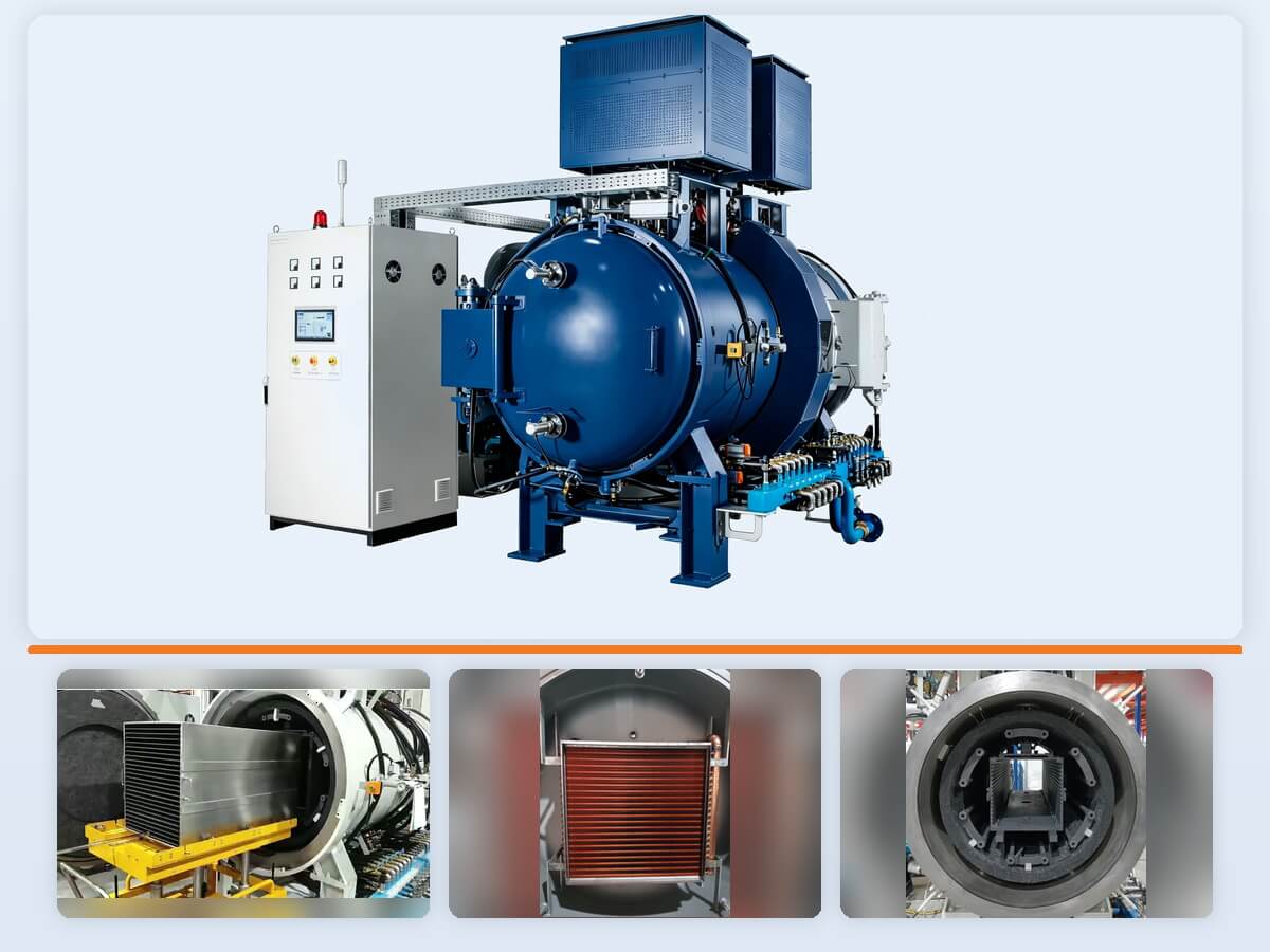
MIM vacuum debinding and sintering furnace with control cabinet and production chamber
5 modelsR&D to mass production
2–6 zonesHeating-zone configurations
7 stagesBinder-vapor management
Selection starts with the process

Six inputs for an accurate furnace configuration

Binder chemistry, alloy, loaded fixture size, gas sequence, thermal cycle, and production target connect your process directly to the chamber and equipment package.

01

Binder and feedstock

Identify the binder family, solvent or thermal pre-treatment, expected vapor load, and any residue or cross-contamination limits.

02

Alloy and atmosphere

Define alloy grade, carbon and oxygen sensitivity, protective or reactive gas requirements, and the intended pressure range for each stage.

03

Part and fixture envelope

Provide the usable load dimensions, gross mass, tray or setter design, part spacing, and representative thermal mass rather than part dimensions alone.

04

Debinding route

Confirm what happens before the furnace, the furnace debinding profile, vapor release rate, purge logic, and cleanout expectations.

05

Thermal cycle and cooling

Share ramp, holds, peak temperature, permitted gradients, cooling end point, cycle-time target, and available cooling-water conditions.

06

Acceptance and throughput

State batch frequency, annual output, temperature-uniformity evidence, vacuum and leak-rate tests, data records, and part-quality acceptance criteria.

Choose an integrated MIM route when

  • Transfer between separate debinding and sintering furnaces creates handling or contamination risk.
  • Binder release is managed through staged collection, cold trapping, accessible drainage, and planned cleaning.
  • One recipe-controlled sequence is preferred for debinding, atmosphere change, sintering, and cooling.
  • A production load can be used to establish the cycle and acceptance plan.

Review another route when

  • Debinding chemistry requires a separate catalytic, solvent, or dedicated pre-treatment system.
  • The load is primarily additive-manufactured metal parts with a different powder-removal and support strategy.
  • Multiple process families need a broader general-purpose furnace rather than a MIM-focused configuration.
  • Part size, floor-loading, or special cooling duty exceeds the current chamber family.
Integrated cycle architecture

A coordinated route from debinding to controlled cooling

The control system coordinates binder release, vapor capture, atmosphere transition, sintering, and cooling as one recipe for each material and part family.

01Load definition
02Controlled debinding
03Vapor capture
04Atmosphere transition
05High-temperature sintering
06Controlled cooling
07Data and part verification

Seven-stage binder-vapor management: three water-cooled collection boxes work with four sequential cold traps to capture binder vapor before it reaches the vacuum pumps. Trap temperatures, cleaning intervals, and cycle settings are matched to the selected binder system.

Configuration logic

Turn process requirements into the right furnace configuration

The matrix links your part, material, and production data to the chamber, vacuum, heating, gas, cooling, and control package.

Scroll horizontally on smaller screens.
Process inputConfiguration impactProject information
Binder system and vapor loadTrap sizing, condensation stages, piping temperature, purge logic, cleaning access, and maintenance interval.Feedstock data, binder fraction, batch mass, release curve, pre-treatment record, and residue limits.
Usable load envelopeHot-zone size, fixture clearance, gas distribution, thermocouple locations, and loading method.Tray drawings, part layout, total load mass, setter material, density of loading, and representative production batch.
Temperature and uniformityHeating-zone count, element layout, insulation thickness, control method, and qualification test points.Peak temperature, ramp and holds, permitted variation, measurement method, load state, and applicable standard.
Vacuum and process gasPump set, valves, pressure control, isolated gas-flow arrangement, gas train, exhaust handling, and safety interlocks.Target pressure by stage, gas type and purity, flow or partial-pressure requirement, leak-rate criterion, and site supply data.
Cooling dutyCopper cooling surfaces, heat exchanger, fan and gas-quench logic, end-point temperature, and water-system interface.Cooling target, load heat capacity, maximum cycle time, inlet water temperature, flow, pressure, and ambient conditions.
Controls and traceabilityPLC/HMI recipe structure, permissions, alarm history, trend recording, data export, and plant-integration boundary.Required tags, sample rate, file format, user levels, communication protocol, language, and retention period.
FAT, SAT, and part qualificationTest load, instrumentation, pass/fail limits, witness points, documentation package, training, and handover.FAT/SAT protocol, calibrated instrument list, sample parts, process indicators, acceptance owner, and deviation process.
Model range

Compare chamber size, heating power, and temperature control

Choose the preliminary model from the loaded fixture envelope, batch mass, binder load, gas distribution, and production target—not the maximum part size alone.

Five configurations from R&D and pilot work to mass-production planning.
ModelMax. temperatureHeating powerHeating zonesTemperature uniformityUsable hot zone (W × L × H)Production range
VF-3361600°C72 kW2≤ ±5°C300 × 300 × 600 mmR&D and pilot work
VF-5561600°C150 kW2≤ ±5°C500 × 500 × 600 mmSmall-batch production
VSF-56161600°C180 kW4≤ ±3°C500 × 560 × 660 mmMedium production loads
VSF-56201600°C210 kW4≤ ±3°C500 × 560 × 660 mmLarge production loads
VSF-7820 PRO1600°C240 kW6≤ ±2°C700 × 780 × 830 mmMass-production planning
Vacuum systemUltimate vacuum ≤ 0.7 Pa, with working pressure configured for each process stage.
Binder managementThree collection boxes plus four sequential cold traps provide seven-stage vapor capture.
Hot-zone packageHard carbon-felt insulation is configured at 40 or 50 mm across the model range.
Controls and continuityPLC + HMI control with ≥ 30-minute compressed-air backup for pneumatic valves and safety functions.

Need a model recommendation?

Send the loaded fixture envelope, batch mass, peak temperature, gas sequence, cooling target, and temperature-uniformity requirement. We will compare the chamber and heating-zone configurations for your production route.

Request a model review
Engineering package

Four systems engineered as one process platform

Flow architecture at a glance Internal process gas, external circulation, and binder vapor follow defined paths so atmosphere control, collection, and maintenance can be configured as one system.
Internal process gasControlled flow through the working load
Metered inlet Hot-zone distribution Loaded fixture Controlled exhaust
External circulationSeparated chamber-side pressure path
External gas inlet Chamber circulation Separated extraction
Seven-stage vapor captureThree collection boxes followed by four cold traps
Under-furnace collection Roots-pump collection Backing-pump collection Cold trap 1 Cold trap 2 Cold trap 3 Cold trap 4 Vacuum pumps
01

Binder-vapor management

Under-furnace, Roots-pump, and backing-pump collection boxes lead into four sequential cold traps. Accessible drainage and cleanout points support planned maintenance for each binder system and cycle.

02

Vacuum and gas separation

Metered internal process gas passes through the load zone, while external circulation follows a separated chamber-side path. The arrangement supports atmosphere stability and reduces cross-contamination risk.

03

Thermal field and hot zone

Two-, four-, and six-zone packages match control density to chamber size. Sensor positions, load fixtures, setpoint, and soak time are integrated into the acceptance plan.

04

Cooling and safety continuity

Copper cooling surfaces support heat transfer, while ≥ 30-minute compressed-air backup maintains pneumatic valve and safety functions during a power interruption.

Material curve library

Material curves for MIM and powder metallurgy

Fifteen named curve profiles cover stainless steels, tool steels, WC-CO, Fe-Ni alloys, magnetic alloys, and titanium alloy. The library gives operators a consistent recipe framework for part-specific cycle setup and repeatable process transfer.

WC-COWC-V1
316L316L-V1
17-417-4-V1
304L304L-V1
420420-V1
SKD11SKD11-V1
Titanium alloyTi-V1
Fe-4Ni / Fe-8NiFeNi-V1
PANACEAPA-V1
GQ4LGQ4-V1
FeCoV185FCV-V1
XH-95XH-95-V1
43404340-V1
82608260-V1
H13H13-V1
FAT / SAT / handover

Build verification into the project plan

The acceptance plan connects furnace performance, controls, process data, and production-part runs with your factory requirements before delivery.

01

Before design freeze

Approve chamber and load drawings, utility limits, gas and exhaust scope, process sequence, safety interlocks, data points, test conditions, and responsibility matrix.

02

During FAT

Record visual and functional inspection, vacuum and leak tests, temperature evidence, alarms, interlocks, recipe operation, data export, and agreed representative-cycle checks.

03

During SAT and ramp-up

Confirm installation, utilities, site safety, operator training, cycle repeatability, maintenance access, spare parts, documentation, and production-part results.

Plan witness points, test records, and handover documents with the vacuum furnace FAT/SAT checklist.

Technical FAQ

Questions to resolve during MIM furnace selection

What information is required to choose a preliminary model?

Provide binder and feedstock data, alloy, tray and part layout, usable load dimensions and mass, debinding and sintering cycle, gas and pressure sequence, cooling target, batch frequency, site utilities, and acceptance criteria. The loaded fixture envelope and thermal mass drive chamber selection.

Can one furnace perform both debinding and sintering?

Yes. The integrated route combines binder removal, vapor capture, atmosphere transition, high-temperature sintering, and cooling in one programmable cycle. The furnace package is matched to the binder system, vapor release, hot-zone materials, and production load.

How does the seven-stage binder-vapor system work?

Three water-cooled collection boxes and four sequential cold traps collect binder vapor in stages before it reaches the vacuum pumps. The system is configured around binder composition, batch mass, vapor-release profile, trap temperature, pressure drop, cleaning access, and maintenance interval.

What does the ≤ 0.7 Pa vacuum value mean for production?

≤ 0.7 Pa is the ultimate-vacuum specification across the five-model range. The pump set and working-pressure control are configured for the binder load, gas sequence, and production cycle.

Can this platform process stainless steel, tool steel, carbide, or titanium alloy?

The material library includes stainless steels, tool steels, WC-CO, Fe-Ni alloys, magnetic alloys, and titanium alloy. Each project aligns the selected curve with feedstock, binder, part geometry, target properties, and production load.

What is included in the project specification?

The project specification covers the usable hot zone, load and fixture envelope, temperature and uniformity test, vacuum and leak-rate criteria, gas system, binder-vapor package, cooling target, controls and data, utilities, safety interfaces, FAT/SAT protocol, documentation, training, warranty, and supplied spares.

Prepare your furnace specification

Send the process details that determine the right furnace

Your process information lets our engineering team match the chamber, binder-vapor system, thermal package, controls, utilities, and acceptance plan to the production line.

  • Binder/feedstock data
  • Alloy and target properties
  • Part and tray drawings
  • Representative load mass
  • Debinding/sintering cycle
  • Gas, pressure, and cooling targets
  • Site utilities and standards
  • FAT/SAT and part criteria
Submit requirements for engineering review
Technical download

MIM Vacuum Debinding & Sintering Furnace Specifications

Download the current reference document or compare all available SYNHTE technical resources.

Contact Us

15+ Years Industrial Experience

Annual output 200+

CE & ISO Certified

Reply within 12 hours

Professional technical support

Free consultation service