info@synthe-corp.com

+86-155-3785-7393

Metal 3D Printing Post-Processing Platform

Additive Manufacturing Sintering Furnace

A configurable 3D printing sintering furnace for additive manufacturing routes that produce binder-jetted and bound-metal green parts. The engineering scope connects feedstock chemistry, debinding route, shrinkage control, hot-zone compatibility and acceptance evidence—before a furnace size or pumping package is fixed.

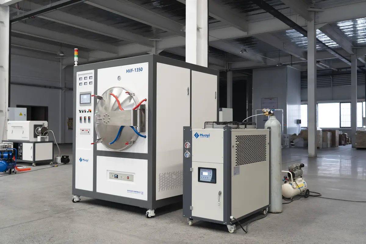
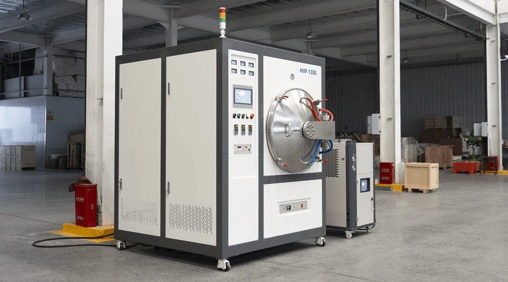
SYNHTE HVF-1350 metal 3D printing and additive manufacturing sintering furnace
SYNHTE HVF-1350 metal 3D printing and additive manufacturing sintering furnace with integrated control cabinet and auxiliary cooling unit.
01 / FeedstockPowder, binder and alloyDefine what must leave the part and what must remain controlled.
02 / Green partEnvelope, mass and geometryEstablish loading, setter and shrinkage risks.
03 / Thermal routeDebind, sinter and coolSeparate external and integrated process steps.
04 / AcceptanceDensity, dimensions and evidenceDefine the evidence used to approve the production load.

Application boundary

Match the metal 3D printing route to the correct furnace process

Metal 3D printing and additive manufacturing cover different consolidation routes. A sintering furnace directly fits Binder Jetting and bound-metal extrusion parts that leave the printer in a green state; LPBF follows a different post-processing route.

Direct fit

Binder Jetting

Printed powder parts contain binder and require a defined post-print route to remove organics and densify the metal structure.

  • Green-part handling and depowdering
  • External or integrated debinding
  • Setter, shrinkage and load qualification
Direct fit

Bound Metal Extrusion / Metal FFF

Polymer-bound metal feedstock produces green parts that must be debound and sintered according to the material supplier’s qualified cycle.

  • Binder chemistry and debinding compatibility
  • Support or separator strategy
  • Controlled shrinkage to final dimensions
Different thermal need

Laser Powder Bed Fusion

LPBF melts and consolidates metal powder during printing. These parts usually follow a separate stress-relief, solution-treatment, aging or HIP route.

  • Confirm the alloy heat-treatment specification
  • Match temperature, atmosphere and cooling requirements
  • Select the appropriate heat-treatment or HIP solution

Confirm your process route first: send us the printing method, feedstock and required final properties. SYNHTE will identify the suitable debinding, sintering or heat-treatment path before configuring the equipment.

Material → process

Translate the 3D printing route into furnace requirements

A production-ready 3D printing furnace specification connects the material supplier’s thermal limits, the real green-part load and the acceptance target. This produces a properly sized vacuum system, compatible hot zone and repeatable debinding and sintering cycle.

Project-specific performance: density, shrinkage and mechanical-property targets are established from the qualified feedstock, part design and agreed acceptance plan.

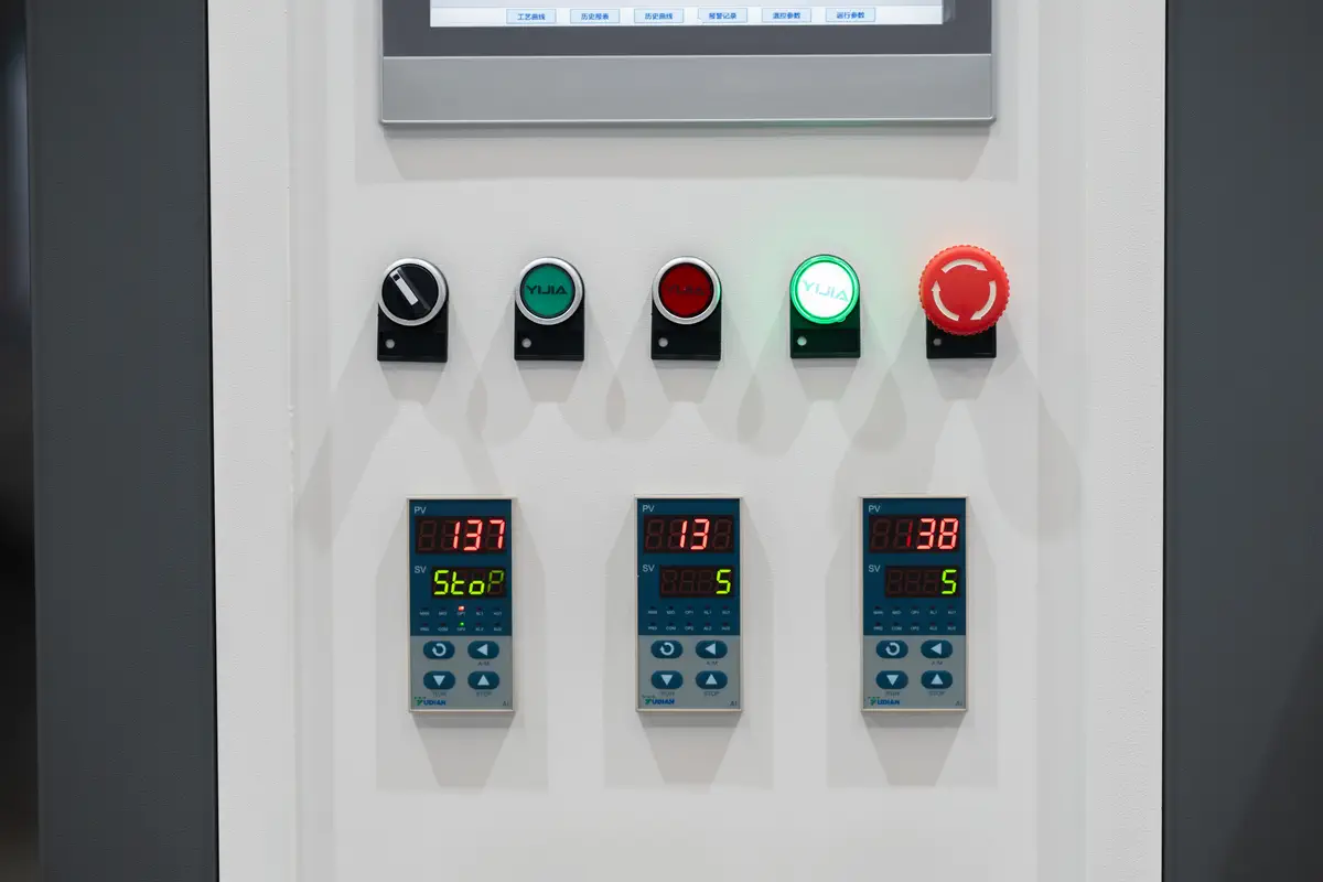
Temperature controllers and operating controls on the HVF-1350 sintering furnace
Integrated temperature control and operating interface support programmable, repeatable debinding and sintering cycles.
01

Feedstock and binder system

State the alloy or ceramic, powder supplier, binder family, green density and the supplier-approved debinding/sintering window. Identify any carbon, oxygen or hydrogen sensitivity.

02

Green-part and batch envelope

Provide maximum part dimensions, green weight, part count per batch, total load, wall-thickness range and fragile features. The working zone is sized around the complete production load and its fixtures.

03

Debinding boundary

Confirm whether catalytic, solvent or thermal debinding occurs externally, or whether controlled thermal debinding must be integrated. Binder vapor volume and allowable removal rate influence exhaust and capture design.

04

Sintering atmosphere and hot zone

Define vacuum, partial pressure, argon, nitrogen, hydrogen or mixed-gas stages. Match graphite or metal hot-zone construction to temperature, cleanliness and material compatibility.

05

Setter, support and shrinkage strategy

Share the print scale factor, expected directional shrinkage, setter material, support interface and loading drawing. Tall, thin, cantilevered and uneven-section parts need early distortion review.

06

Acceptance evidence

Define density method, dimensional sampling, visual criteria, witness coupons, material tests, temperature survey and required FAT/SAT records before the equipment is released.

Binder removal strategy

Control what leaves the green part before densification begins

Successful binder removal coordinates heating rate, gas flow, pressure, part thickness, load density and vapor handling. The result is a clean, stable brown part ready for controlled densification.

Choose external or integrated debinding

External catalytic or solvent debinding may deliver a brown part ready for sintering. Integrated thermal debinding can reduce transfers but must be compatible with binder chemistry, chamber cleanliness and service intervals.

Define controlled binder removal

Use feedstock evidence to set staged heating, holds, pressure and gas exchange. Thick sections and dense loads generally require a different removal strategy from thin coupons.

Capture condensable vapor and protect the vacuum train

Condenser, trap, filter, exhaust path and clean-out access are configured around expected binder mass and condensate behavior to support stable pumping and maintainable production.

Verify before high-temperature sintering

Where the process requires it, debinding completion is checked through weight loss, witness samples, off-gas behavior or the material supplier’s specified method before the densification stage.

HVF-1350 additive manufacturing sintering furnace with cooling and gas connection equipment
HVF-1350 system view with furnace cabinet, cooling unit and gas connection. Vacuum and vapor-management modules are configured for the selected binder route and production load.

Inputs for vapor-management sizing

Binder mass
Per part and per maximum batch
Removal route
Catalytic, solvent, thermal or combined
Condensate
Expected species, temperature and service access
Facility
Exhaust, gas detection and local safety rules

Atmosphere and hot-zone selection

Configure the 3D printing sintering furnace around material sensitivity

Stainless steel, tool steel, nickel alloy, titanium and refractory materials each require a compatible hot zone, atmosphere and cleanliness strategy. Material chemistry and the target cycle guide the configuration.

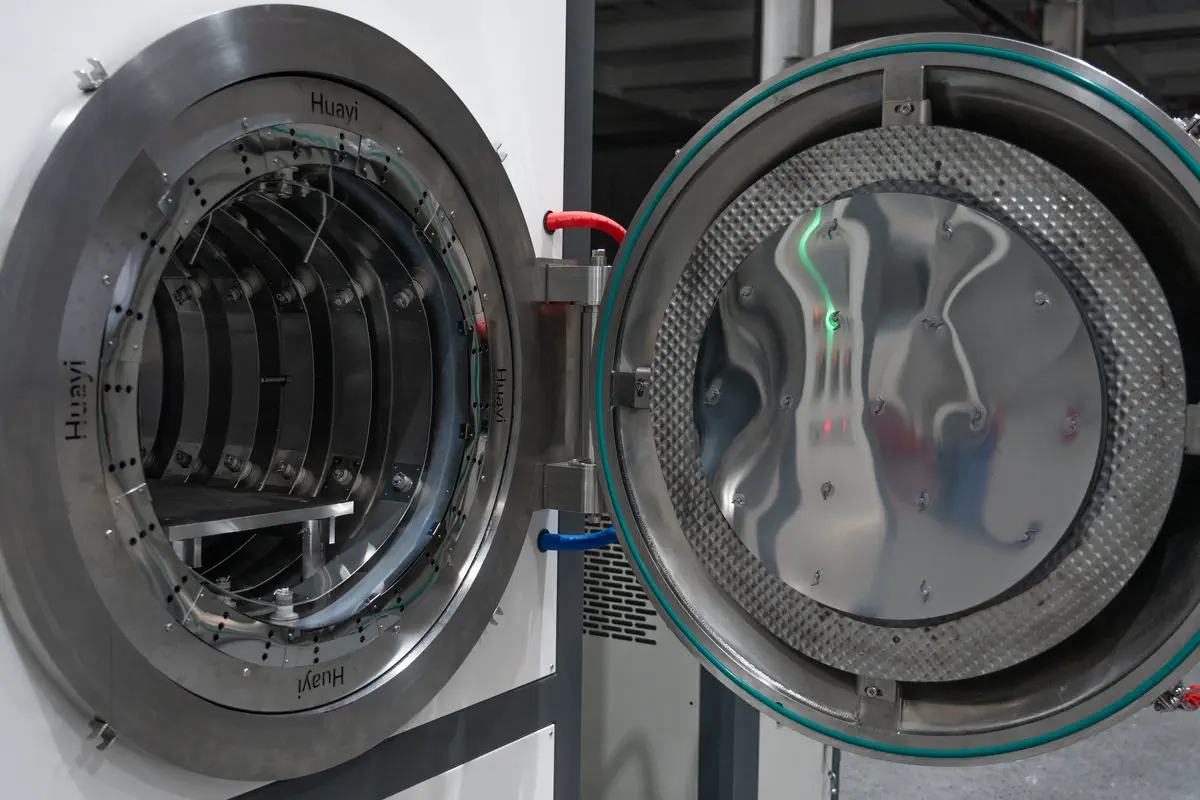
Open metal hot zone and loading shelf inside the HVF-1350 sintering furnace
Actual HVF-1350 metal hot zone with shielded heating chamber and loading shelf, suited to clean controlled-atmosphere processing within its qualified temperature range.

Hot-zone decision path

Graphite hot zone: often selected for high-temperature capability and thermal efficiency. Review carbon potential, insulation dust, setter compatibility and any material-specific contamination limit.

Metal hot zone: molybdenum shields and heating elements can support clean processing for compatible temperature ranges. Review alloy reactions, oxygen control, maximum service temperature and maintenance requirements.

Atmosphere: vacuum, partial pressure, inert or reducing gas stages are chosen by material and binder route. Hydrogen service includes the required facility review, gas controls and safety interlocks.

Swipe horizontally to view the full table →

HVF-1350 reference AM metal-hot-zone configuration
ItemCurrent referenceHow to qualify it for your project
Maximum temperature1550°CConfirm against alloy, hot-zone life, loaded cycle and required margin.
Recommended long-term temperature1350°CReference rating for this metal-hot-zone configuration; alternative temperature ranges are engineered by model.
Effective working zone400 × 250 × 250 mmValidate usable load envelope, fixtures, setter clearance and thermocouple positions; custom sizes are available.
Hot-zone construction3-layer molybdenum shield + 3-layer stainless insulation; molybdenum heating elementsReview carbon/oxygen sensitivity, temperature range and maintenance plan before freezing construction.
Temperature control±1°C controller accuracyLoaded temperature uniformity is specified through an agreed survey method, sensor layout and acceptance band.
Control interfacePID control, 7-inch touchscreen, 30+ recipesConfirm recipe permissions, data logging, alarms, traceability and interface language.
Vacuum systemUp to a three-stage pumping packageFinal pump combination and vacuum target depend on binder load, gas stages, cleanliness and cycle time.

These values describe the HVF-1350 reference configuration. Final specifications, performance tolerances and utility loads are confirmed in the project technical agreement.

Load and shrinkage control

Design the working zone around a qualified production load

The usable batch combines parts, setters, supports, spacing and gas-flow paths. Sizing the chamber from the complete load helps maintain consistent debinding, shrinkage and cooling across production batches.

Map the load envelope

Provide the largest part, typical part family, stacking rules, tray count, total green mass and expected batch frequency. Reserve clearance for fixtures, flow and survey sensors.

Protect unsupported geometry

Review cantilevers, thin walls, top-heavy features, transitions and internal channels. Setter shape, support interface and release material must match the feedstock supplier’s route.

Control directional shrinkage

Use printed scale factors and measured coupons to distinguish X/Y/Z behavior, then qualify shrinkage for each geometry, print orientation and material batch.

Qualify heating and cooling with the load

Ramp rate, holds, gas flow and cooling sequence should be verified on a representative load. The acceptance plan records where samples and thermocouples are placed.

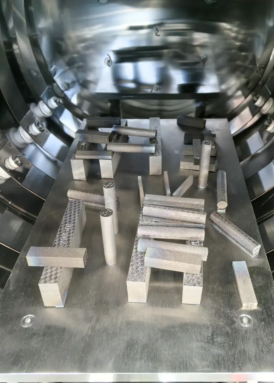
Additively manufactured metal samples arranged on setters inside the HVF-1350 furnace
Real metal AM sample geometries arranged inside the furnace. Final setter, support and spacing plans are matched to the qualified production part family.

Configuration → acceptance

Specify what the furnace must prove before delivery

A useful FAT/SAT plan turns density, dimensional and temperature-uniformity targets into measurable, project-specific evidence.

01 / Recipe

Cycle reproducibility

Verify programmed ramps, holds, pressure/gas transitions, alarms and recipe protection.

02 / Thermal

Temperature evidence

Agree empty or loaded survey conditions, sensor locations, operating point and allowed deviation.

03 / Part

Density and dimensions

Define test method, sampling plan, datum scheme and accepted shrinkage/warpage by part family.

04 / Material

Material-specific results

Use approved witness coupons or parts for chemistry, microstructure or mechanical tests where required.

05 / System

Vacuum and gas functions

Verify leak rate, pump-down behavior, gas controls and interlocks against the signed scope.

06 / Handover

FAT, SAT and records

Define manuals, drawings, calibration records, training, spares and site acceptance responsibilities.

Recommended acceptance hierarchy

Level 1
Equipment functions, safety logic and utilities
Level 2
Vacuum, gas and temperature performance under agreed conditions
Level 3
Representative load cycle and process records
Level 4
Customer-defined part or coupon evidence

Part results depend on feedstock, printing, debinding, loading and thermal processing together. The acceptance plan connects each target to a clear test method, sample location and evidence record.

Frequently asked questions

Questions to settle before furnace selection

Which metal 3D printing processes need a sintering furnace?

Binder Jetting and bound-metal extrusion or Metal FFF normally produce green parts that require debinding and sintering. LPBF parts are already consolidated by laser melting during printing and usually follow a heat-treatment, stress-relief or HIP route instead.

Can debinding and sintering be integrated in one furnace?

They can be integrated when the binder chemistry, vapor load, chamber cleanliness, pumping protection and maintenance plan are compatible. Other feedstocks require external catalytic or solvent debinding before sintering.

Should I choose a graphite or molybdenum hot zone?

The choice depends on sintering temperature, alloy chemistry, carbon and oxygen limits, atmosphere, fixture materials and service plan. SYNHTE reviews these inputs before fixing the hot-zone construction.

How is AM-part shrinkage controlled?

Use the feedstock supplier’s baseline together with printed coupons and representative parts. Print orientation, geometry, green density, setters, support and thermal cycle can all influence directional shrinkage and distortion.

What information is required for a quotation?

Provide AM process, material/feedstock, binder and debinding route, largest green part, batch load, target cycle, atmosphere, final density/dimensional criteria, utilities and required FAT/SAT records.

Is the 400 × 250 × 250 mm working zone fixed?

The working zone is configurable. The 400 × 250 × 250 mm size is the HVF-1350 reference configuration, while the final size is selected from the qualified load envelope, fixtures, clearance, production volume and temperature-survey plan.
Qualified RFQ

Send the process inputs—not only a chamber size

With the information at right, SYNHTE can return a project-specific thermal route, hot-zone recommendation, pumping and gas scope, load concept and acceptance plan.

01
3D printing route and printerBinder Jetting, Metal FFF or another bound-powder additive route.
02
Feedstock and binderSupplier, grade, chemistry and approved process window.
03
Green-part envelopeMaximum size, weight, geometry and batch quantity.
04
Debinding routeExternal or integrated; expected binder mass per load.
05
Thermal and gas cycleTemperature, holds, vacuum/pressure and gas stages.
06
Setter and loadingTray, support, separator and qualified load drawing.
07
Acceptance targetsDensity, dimensions, evidence and FAT/SAT scope.
08
Site conditionsPower, water, gases, exhaust and safety requirements.
Technical download

HVF Additive Manufacturing Sintering Furnace Specifications

Download the current reference document or compare all available SYNHTE technical resources.

Contact Us

15+ Years Industrial Experience

Annual output 200+

CE & ISO Certified

Reply within 12 hours

Professional technical support

Free consultation service