info@synthe-corp.com

+86-155-3785-7393

SYNHTE Vacuum Furnace Systems

Vacuum Sintering Furnace Systems

Vacuum sintering systems combine controlled heating, vacuum or process gas, load handling and cycle evidence to densify metal or ceramic green parts. Configuration begins with the material, forming route, binder load, usable work zone and required result.

  • Pressed metals, refractory powders and hardmetals
  • MIM and binder-based additive manufacturing
  • Oxide, non-oxide ceramic and composite routes
  • Pressureless, controlled-gas and hot-press densification
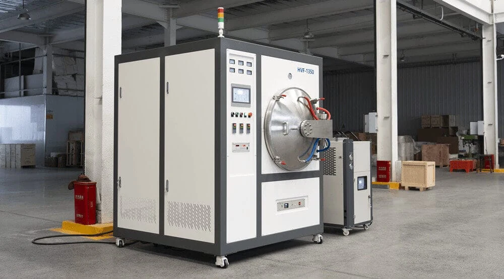
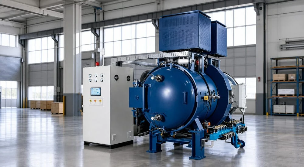
SYNHTE vacuum debinding and sintering furnace in an industrial workshop
Vacuum debinding and sintering system
Materials and forming routesPressed powder, MIM, hardmetals, ceramics and binder-based additive manufacturing
Furnace configurationFront-loading, debinding, bottom-loading, tube-atmosphere and hot-press systems
Qualification and deliveryWork zone, atmosphere, utilities, technical agreement, FAT, records and SAT
Materials and forming routes

Sintering applications across metals, hardmetals and ceramics

Material chemistry, green-part formation and densification route determine the hot zone, atmosphere, debinding system, loading arrangement and acceptance evidence.

01

Pressed metal and refractory powders

Ferrous, stainless, copper-base, nickel-base and refractory-metal powder routes require chemistry-specific vacuum, gas and hot-zone conditions.

  • Alloy grade, particle system, lubricant and green density
  • Batch mass, tray contact, target density and dimensional change
  • Carbon, oxygen, volatilization and distortion limits
02

Cemented carbide and cermet

Hardmetal routes such as WC-Co and cermet systems depend on carbon control, binder phase, vacuum or partial pressure and load consistency.

  • Carbide or cermet composition and binder percentage
  • Carbon-window, porosity, density and grain-growth criteria
  • Setter material, load geometry and binder-vapor management
03

Metal injection molding

MIM parts require the feedstock, upstream solvent or catalytic stage and residual thermal debinding load to be engineered as one route.

  • Feedstock grade, binder chemistry and pre-debinding stage
  • Residual binder mass, vapor path, trap and cleaning access
  • Shrinkage, density, carbon and recurring defect criteria
04

Binder-based additive manufacturing

Binder jetting and material extrusion produce metal or ceramic green parts with route-specific support, debinding and shrinkage behavior.

  • Printing route, powder or feedstock and green density
  • Support strategy, tray nesting and fragile-part handling
  • Directional shrinkage, distortion and lot repeatability
05

Oxide ceramics

Alumina, zirconia and related oxide routes require atmosphere, setter and contamination decisions matched to oxygen balance and final properties.

  • Ceramic grade, additives, binder and forming method
  • Setter, powder contact, atmosphere and cleanliness
  • Density, grain, color, dimensions and defect criteria
06

Non-oxide ceramics and composites

SiC, Si3N4, AlN, B4C and composite routes may require controlled gas, partial pressure or applied force.

  • Powder system, sintering aids and volatile species
  • Vacuum, nitrogen or argon route and hot-zone compatibility
  • Pressureless, gas-assisted or hot-press densification

Process routes covered by the configuration range

Pressureless batch sinteringVacuum or partial-pressure cycles for trays, fixtures and repeatable production loads.
Thermal debinding and sinteringIntegrated binder removal with vapor collection, trap access and controlled heating ramps.
Controlled-gas processingNitrogen, argon or hydrogen routes with defined purity, purge, flow, exhaust and safety logic.
Pressure-assisted densificationVacuum hot pressing when force, tooling and a synchronized temperature-pressure cycle are required.
Selection path

How does the process become a furnace configuration?

Six engineering gates connect the green part and required result to a standard platform with options or a project-specific configuration.

Material and forming route

Identify powder or ceramic grade, part geometry, forming method and the required final properties.

Debinding requirement

Decide whether thermal binder removal belongs in the furnace and how vapors must be trapped and exhausted.

Pressure requirement

Separate pressureless sintering from processes that require force, tooling and a temperature-pressure sequence.

Atmosphere and hot zone

Match vacuum, N2, Ar or H2, purge logic and graphite or molybdenum compatibility to the material.

Work zone and loading

Size the usable zone around the real tray, fixture, batch mass, load center and front, bottom or tube access.

Acceptance plan

Define test conditions, records, FAT, shipment handover and SAT before the technical scope is frozen.

Configuration routes

Compare vacuum sintering furnace configurations

Four batch-system platforms cover conventional, debinding, additive and bottom-loading requirements. Tube and hot-press systems address controlled gas flow or applied-force processes.

Batch-system starting points
SYNHTE multipurpose vacuum sintering furnace Configurable batch platformMultipurpose vacuum sintering furnace

A flexible starting platform for defined powder-metal, carbide, ceramic or development-to-production batch processes.

Best for
Pressureless batch sintering with a defined vacuum or protective-gas route.
Not first
High binder loads without a qualified vapor path, or cycles that require applied force.
Confirm
Material, hot zone, work zone, load mass, vacuum/gas recipe, cooling and test basis.
Explore the multipurpose furnace
SYNHTE MIM debinding and sintering furnace Integrated binder controlMIM debinding and sintering furnace

For MIM production where thermal debinding, vapor capture, atmosphere control and sintering must be engineered as one route.

Best for
Qualified feedstock with known binder stages, green loading and shrinkage targets.
Not first
An unknown binder or a process that omits required upstream pre-debinding.
Confirm
Binder chemistry, mass per load, traps, gas flow, fixtures, density and defect criteria.
Explore the MIM debinding furnace
SYNHTE additive manufacturing sintering furnace Binder-based additive routeAdditive manufacturing sintering furnace

For binder-jetted or material-extruded green parts where support, debinding, shrinkage and distortion need a controlled window.

Best for
Repeatable printed feedstock, known green density and a documented support strategy.
Not first
Direct metal laser processes that do not produce binder-containing green parts.
Confirm
Print route, binder, green part, tray nesting, shrinkage, output and acceptance samples.
Explore the additive sintering furnace
SYNHTE bottom-loading vacuum sintering furnace Heavy or tall load architectureBottom-loading vacuum sintering furnace

For tall, heavy or vertically handled loads where carrier stability, center of mass and the loading path determine the furnace structure.

Best for
Large vertical work zones, heavy fixtures and controlled bottom-entry handling.
Not first
Small batches that can be loaded safely and efficiently into a horizontal chamber.
Confirm
Load drawing, mass and center, carrier, lift stroke, site clearance, floor and utility data.
Explore the bottom-loading furnace
Specialized process alternatives
SYNHTE atmosphere tube furnace Controlled gas routeAtmosphere tube furnace

A specialized route when gas composition, tube flow, purge sequence and exhaust control are central to the process.

Best for
Defined protective or reducing gas processing with compatible tube and boat geometry.
Not first
Large batch loads or projects that need a conventional high-vacuum chamber.
Confirm
Gas recipe, purity, flow, tube, exhaust, detection, interlocks and safety standard.
Explore the atmosphere tube furnace
SYNHTE vacuum hot press furnace Pressure-assisted densificationVacuum hot press furnace

A specialized system when force, tooling and a combined temperature-pressure program are required during the thermal cycle.

Best for
Pressure-assisted densification with defined graphite tooling and specimen geometry.
Not first
Pressureless batch sintering where tooling and force add no process benefit.
Confirm
Force, die drawing, ram travel, alignment, temperature, vacuum and accepted sample.
Explore the vacuum hot press furnace
Batch-system starting points
SYNHTE multipurpose horizontal vacuum sintering furnace
Configurable batch platform

Multipurpose vacuum sintering furnace

A flexible starting platform for defined powder-metal, carbide, ceramic or development-to-production batch processes.

Best for
Pressureless batch sintering with a defined vacuum or protective-gas route.
Not first choice
High binder loads without a qualified vapor path, or cycles that require applied force.
Confirm
Material, hot zone, work zone, load mass, vacuum/gas recipe, cooling and test basis.
Explore the multipurpose furnace
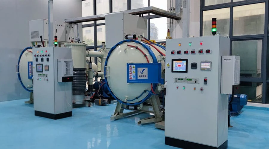
SYNHTE MIM vacuum debinding and sintering furnace in an industrial workshop
Integrated binder control

MIM debinding and sintering furnace

For MIM production where thermal debinding, vapor capture, atmosphere control and sintering must be engineered as one route.

Best for
Qualified MIM feedstock with known binder stages, green loading and shrinkage targets.
Not first choice
An unknown binder or a process that omits required upstream solvent or catalytic debinding.
Confirm
Binder chemistry, mass per load, traps, gas flow, fixtures, density and defect criteria.
Explore the MIM debinding furnace
SYNHTE furnace for binder-based additive manufacturing green parts
Binder-based additive route

Additive manufacturing sintering furnace

For binder-jetted or material-extruded green parts where support, debinding, directional shrinkage and distortion need a controlled window.

Best for
Repeatable printed feedstock, known green density and a documented support strategy.
Not first choice
Direct metal laser processes that do not produce binder-containing green parts.
Confirm
Print route, binder, green part drawing, tray nesting, shrinkage, output and acceptance samples.
Explore the additive sintering furnace
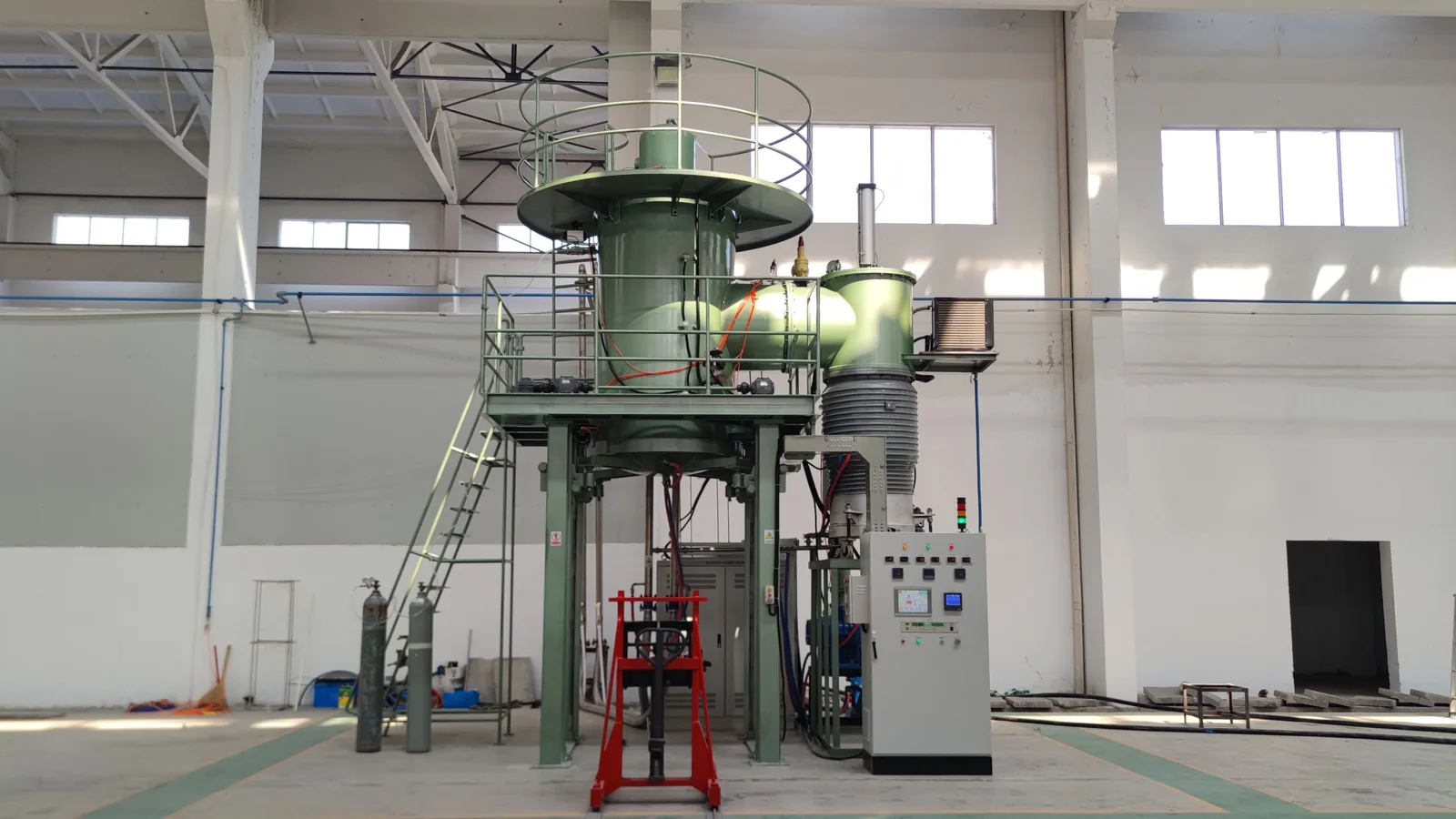
Large vertical bottom-loading vacuum sintering furnace
Heavy or tall load architecture

Bottom-loading vacuum sintering furnace

For tall, heavy or vertically handled loads where carrier stability, center of mass and the loading path determine the furnace structure.

Best for
Large vertical work zones, heavy fixtures and controlled bottom-entry handling.
Not first choice
Small batches that can be loaded safely and efficiently into a horizontal chamber.
Confirm
Load drawing, mass and center, carrier, lift stroke, site clearance, floor and utility data.
Explore the bottom-loading furnace
Specialized process alternatives
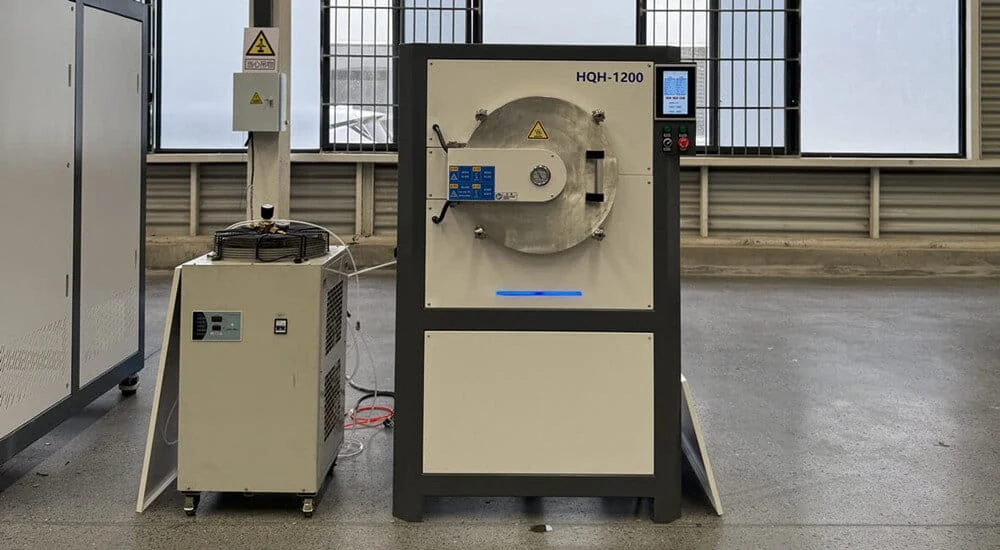
SYNHTE atmosphere tube furnace with gas-control and cooling unit
Controlled gas route

Atmosphere tube furnace

A specialized route when gas composition, flow through a tube, purge sequence and exhaust control are central to the process.

Best for
Defined protective or reducing gas processing with compatible tube and loading-boat geometry.
Not first choice
Large batch loads or projects that need a conventional high-vacuum chamber platform.
Confirm
H2, N2 or Ar recipe, purity, flow, tube, exhaust, detection and safety standard.
Explore the atmosphere tube furnace
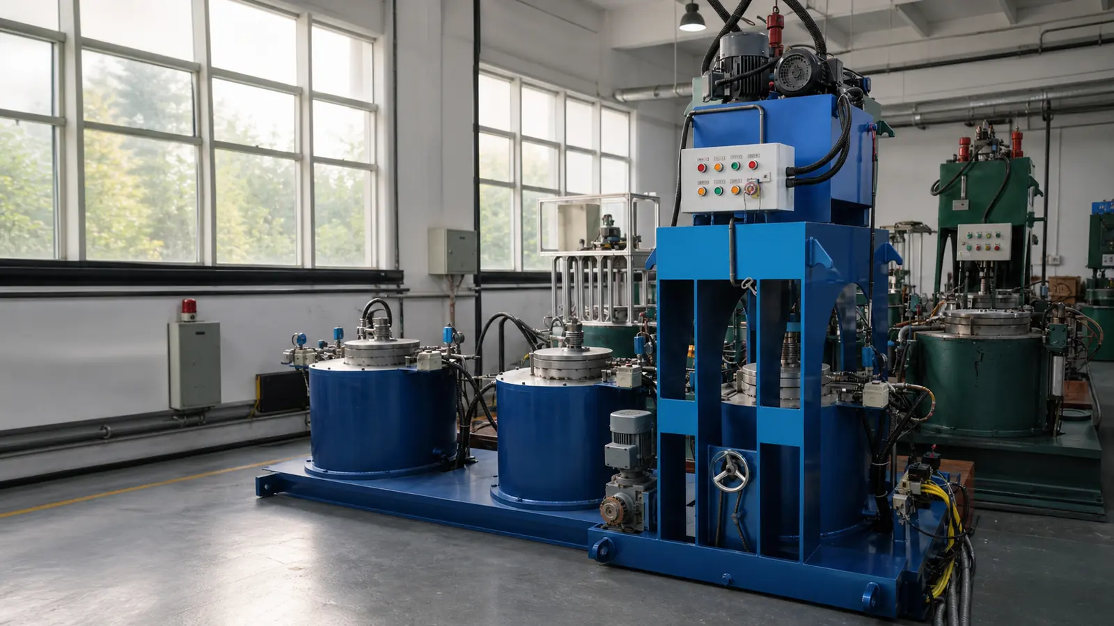
SYNHTE VMPE vacuum hot press furnace in the production workshop
Pressure-assisted densification

Vacuum hot press furnace

A specialized system when force, tooling and a combined temperature-pressure program are required during the thermal cycle.

Best for
Pressure-assisted densification with defined graphite tooling and specimen geometry.
Not first choice
Conventional pressureless batch sintering where tooling and force add no process benefit.
Confirm
Force, die drawing, ram travel, alignment, temperature, vacuum and accepted test sample.
Explore the vacuum hot press furnace
Debinding, hot zone and atmosphere

Define the thermal process and equipment functions

A complete sintering system aligns debinding, heating, vacuum or process gas, cooling, controls and maintenance access with the material and production load.

Debinding and vapor management

Upstream solvent or catalytic treatment, residual binder mass, heating ramps, vapor path, condenser or trap capacity and cleaning access define the debinding package.

Hot zone and heating system

Graphite or molybdenum hot-zone selection follows operating temperature, carbon sensitivity, cleanliness, heating-zone count, insulation and maintenance requirements.

Vacuum pumping and partial pressure

Pump train, base and working vacuum, pressure-rise criterion, partial-pressure control, condensable load and isolation logic are matched to the cycle.

Controlled atmosphere and gas safety

N2, Ar or H2 composition, purity, pressure, flow, purge, exhaust, gas detection and interlocks are defined with destination requirements.

Cooling and cycle endpoint

Cooling gas, pressure, circulation, fan logic, load heat capacity, discharge temperature and cycle-time target establish the cooling package.

Controls, recipes and records

Heating ramps, dwell segments, pressure and gas sequences, alarms, permissions, trend data and export format form the process-control record.

Multipurpose batch platformGraphite and molybdenum versions list maximum temperatures of 2200°C and 1300°C, effective areas from 300 × 300 × 450 mm to 800 × 800 × 1200 mm, and load references from 100 to 800 kg.
MIM debinding platformThe five-model range lists 1600°C maximum temperature, 2-6 heating zones and hot zones from 300 × 300 × 600 mm to 700 × 780 × 830 mm.
Vacuum hot-press platformThe VMPE 100T configuration lists 100-ton rated force, 1600°C maximum temperature and a Ø155 × 50 mm uniform zone.
Bottom-loading platformPublished work-zone examples extend from Ø350 × H400 mm to Ø2.3 m × H1.4 m for vertically handled loads.
Work zone and loading

Size the usable work zone around the real load

The usable or qualified work zone is not the chamber diameter. It is the defined space in which the agreed temperature and process conditions are evaluated. Include the part, tray, fixture, support, clearance and center of mass.

Front-loading batch

Confirm door clearance, tray or trolley, fixture footprint, batch mass and the operator or handling path.

Bottom-loading vertical

Confirm load center, carrier stability, lift stroke, pit or floor interface, overhead clearance and service access.

Tube and loading boat

Confirm tube inside diameter, heated length, boat material, part spacing, gas flow path and safe access.

Throughput basis

State acceptable parts per tray, kilograms per batch, cycles per shift, cooling endpoint and planned annual output.

FAT, delivery and SAT

Agree how the furnace will be accepted before fabrication

Equipment acceptance and customer-part process qualification are related but different. Define responsibilities, test conditions, records and pass/fail criteria in the technical agreement rather than relying on a generic specification line.

Technical agreement

Freeze configuration, work zone, utilities, interfaces, process functions, exclusions, documents and acceptance responsibilities.

Factory acceptance test

Specify vacuum and pressure-rise tests, temperature evidence, controls, alarms, interlocks, gas-system checks and any agreed loaded cycle.

Delivery readiness

Review serial identity, packing, drawings, manuals, spare parts, destination utilities, installation scope and shipment protection.

Site acceptance test

Define utility checks, commissioning, training, repeat tests, data handover and the site criteria that close the equipment scope.

Scope before purchase order

Make documentation and service boundaries reviewable

Proposal scope can cover equipment definition, records, acceptance evidence, destination interfaces, installation and operating support.

Equipment definition

General arrangement, work-zone definition, process flow or P&ID, electrical interface and utility list.

Controls and records

Recipe functions, alarm and interlock list, data recording, user levels and agreed export format.

Acceptance evidence

Approved FAT protocol, test instruments, raw records, result summary and open-item closure method.

Destination requirements

Supply voltage and frequency, electrical standard, gas and cooling-water conditions, exhaust and plant safety interfaces.

Shipment and installation

Packing, foundation or floor data, lifting plan, assembly boundary, commissioning prerequisites and site readiness.

Operation and support

Manuals, training, recommended spare parts, warranty scope and remote or on-site support boundary.

After the inquiry

What happens after you share the application?

The first response narrows the configuration and identifies the engineering inputs needed for a technically aligned proposal.

STEP 01

Application review

Material, green part, binder, load and required result are checked for route compatibility.

STEP 02

Clarification list

Open questions on atmosphere, work zone, utilities, output and acceptance are returned for confirmation.

STEP 03

Technical proposal

The proposed system, options, exclusions, interfaces and preliminary acceptance basis are aligned.

STEP 04

Agreement and tests

Final values, responsibilities, documentation, FAT and SAT are frozen before manufacture proceeds.

Engineering RFQ

What information is needed for a relevant proposal?

Prepare the essentials below and include them in the project message. When a drawing or process specification is available, mention it so an appropriate file-transfer method can be agreed.

Engineering questions

Vacuum sintering furnace FAQ

Common selection questions covering debinding, hot zones, atmosphere, work zone, acceptance and site utilities.

Can debinding and sintering be completed in one furnace?

They can be integrated when the feedstock, upstream pre-debinding, remaining binder mass, vapor collection, cleaning access and cycle are qualified together. Not every binder is suitable for the same trap or one-step route.

How do graphite and molybdenum hot zones differ?

Graphite supports higher published temperatures on the multipurpose platform, while molybdenum can suit processes that require a metal hot zone. Carbon sensitivity, material compatibility, cleanliness, temperature and maintenance determine the choice.

What is the usable work zone?

It is the agreed space in which the specified process or temperature condition is evaluated. It is smaller than the chamber and must include the real fixture, tray, support and clearances.

Can the system use nitrogen, argon or hydrogen?

N2, Ar and H2 options depend on material compatibility and the selected furnace. Gas purity, pressure, flow, purge, exhaust, detection, interlocks and destination safety requirements must be confirmed.

What should a furnace FAT include?

Typical equipment checks can cover vacuum or pressure rise, temperature evidence, control functions, alarms, interlocks, gas systems and records. The protocol must state instruments, work zone, temperature, dwell, empty or loaded condition and pass/fail criteria.

Does equipment acceptance qualify my parts?

Not automatically. Equipment FAT verifies the agreed furnace scope. Part density, shrinkage, microstructure, chemistry and defects require a separate sample plan, material route and acceptance method if they are part of the project.

What utilities and site data are needed?

Provide supply voltage and frequency, available power, cooling-water conditions, compressed air, process gases, exhaust, floor or foundation data, installation access and local electrical and safety requirements.

What should I send with the first inquiry?

Send the material and forming route, binder steps, part and fixture envelope, batch mass, temperature and atmosphere, output target, utilities, destination and required FAT/SAT evidence. Drawings and defect history improve the review.

Next step

Turn the material, load and acceptance plan into a furnace configuration

Share the green part, binder route, usable work-zone envelope, load mass, atmosphere, temperature and output target. The engineering review can then identify a suitable starting platform and the items that still require confirmation.

Contact Us

15+ Years Industrial Experience

Annual output 200+

CE & ISO Certified

Reply within 12 hours

Professional technical support

Free consultation service