
Vacuum Heat Treatment Distortion Control: Fixturing, Loading and Cooling
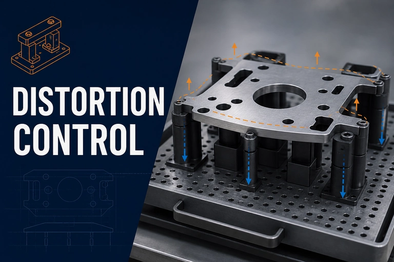
Vacuum heat treatment distortion control starts with a balanced combination of part support, load symmetry, thermal exposure and cooling conditions. Treat the fixture and load as process controls, not as separate handling details.
Vacuum Heat Treatment Distortion Control: First Checks
Vacuum processing can help protect surface condition, but it does not eliminate distortion risk. Shape change is governed by the alloy, starting condition, section changes, residual stress, fixture support, heating and cooling uniformity, and the approved cycle. The effective control is a qualified system of part design, loading practice and process verification.
Why parts move during heat treatment
Components can move when different regions heat or cool at different rates, when phase changes are uneven, or when machining and forming stresses are released. Thin sections, long unsupported spans, asymmetric shapes, sharp section transitions and stacked loads are especially sensitive. A bright, clean surface after a vacuum cycle does not demonstrate dimensional stability on its own.
Begin with the part drawing and the critical dimensions. Decide which faces may be supported, which must remain free, where thermal mass differs and which distortion modes are unacceptable. That information should guide the fixture and the process trial before production is released.
Fixture principles that support repeatability
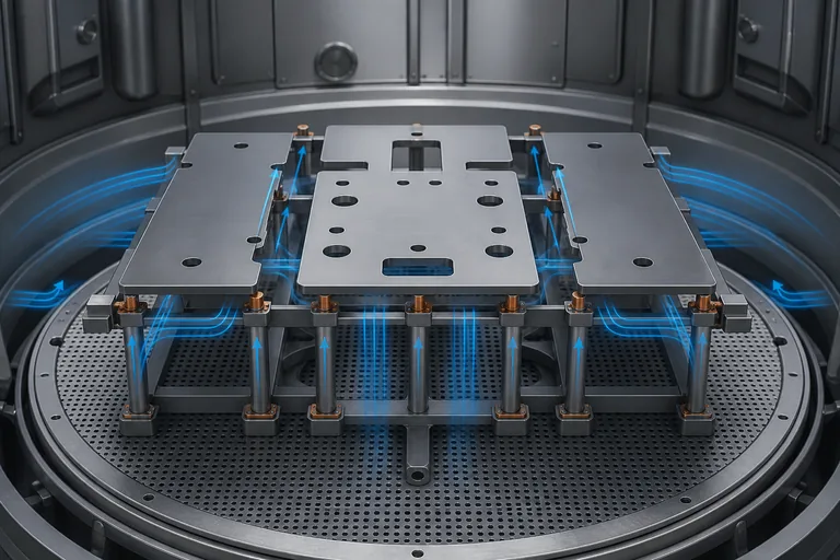
The fixture view shows how support locations and open paths work together to reduce uneven heating and cooling effects.
| Decision | Useful aim | Risk when ignored |
|---|---|---|
| Support points | Support the part without over-constraining thermal movement | Local sagging, imprinting or stress concentration |
| Material and cleanliness | Use qualified fixture materials and clean surfaces | Contamination, reaction or inconsistent heat transfer |
| Load spacing | Leave paths for radiation and quench-gas circulation | Uneven heating or cooling across the load |
| Orientation | Place sensitive geometries in a repeatable, documented position | Part-to-part variation from changing gravity and flow effects |
| Thermal mass | Keep mixed-mass loads within the qualified process envelope | Different response between heavy and light components |
Loading and cooling are part of the recipe
For gas quenching, the selected gas is only one part of the cooling result. Fixture openness, basket design, nozzle paths, load spacing, part orientation and pressure profile all affect the heat extracted from individual surfaces. Review the Nitrogen vs Argon for Vacuum Gas Quenching guide for the gas-selection question; use this article to make the load repeatable after that choice is made.
Do not move a component from a flat tray to a deep basket, increase load density or change fixture material without considering whether the qualification still represents the production condition. Small changes can alter local cooling or support more than a headline furnace setting suggests.
Build a distortion-control qualification loop
- Define the critical dimensions, flatness, runout or positional tolerances before the trial.
- Document starting material condition, machining sequence and stress-relief history.
- Use a controlled fixture, load map and location in the qualified work zone.
- Record the thermal recipe and gas-quench conditions.
- Measure the finished part at the agreed features and compare repeated loads.
- Freeze the validated setup; review any material, fixture, load or recipe change before release.
Temperature uniformity is one input to this work, not the complete answer. See the Vacuum Furnace Temperature Uniformity and TUS Guide for the difference between furnace-level evidence and part qualification.
Distortion-sensitive work needs more than a nominal chamber size. Define the usable work zone, loading route, fixture envelope, heat-up and cooling control, and the records used to protect a qualified recipe. For broader equipment selection, start with Vacuum Furnace Systems, then review the Vacuum Heat Treatment Furnace system family; when rapid gas cooling is central to the distortion strategy, compare the Vacuum Gas Quenching Furnace.
Vacuum Heat Treatment Furnace
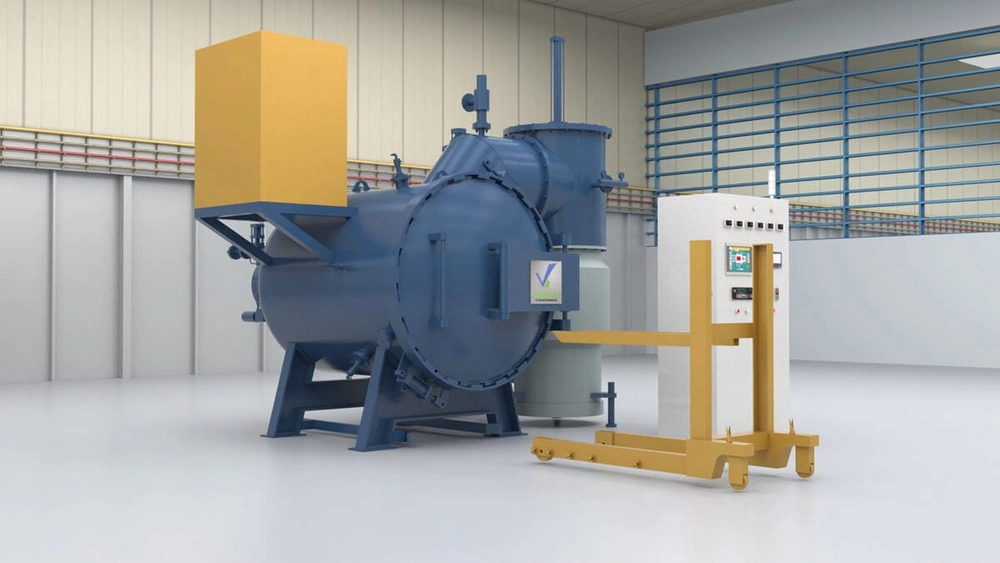
A configured furnace should be evaluated with the part, fixture and cooling requirement so the qualified load can be repeated in production.
- Work-zone and load-envelope definition
- Controlled heating and gas-quench options
- Process data for qualification records
What to include in your enquiry
Share enough detail to evaluate the part and load instead of only the furnace temperature.
- Material grade, drawing, critical dimensions and distortion limits
- Part geometry, wall thickness, load mass and production quantity
- Fixture drawing, support points and required orientation
- Heat-treatment cycle, quench method and cooling-rate requirement
- Inspection plan, data record and acceptance criteria
Technical references
- AIAG CQI-9 — Special Process: Heat Treat System Assessment — official AIAG reference for evaluating controlled heat-treatment systems and process evidence.
- SAE AMS2750 — Pyrometry — official SAE scope for furnace and pyrometric control and testing.