
Vacuum Furnace Cooling-Water Interlocks: Commissioning and Acceptance
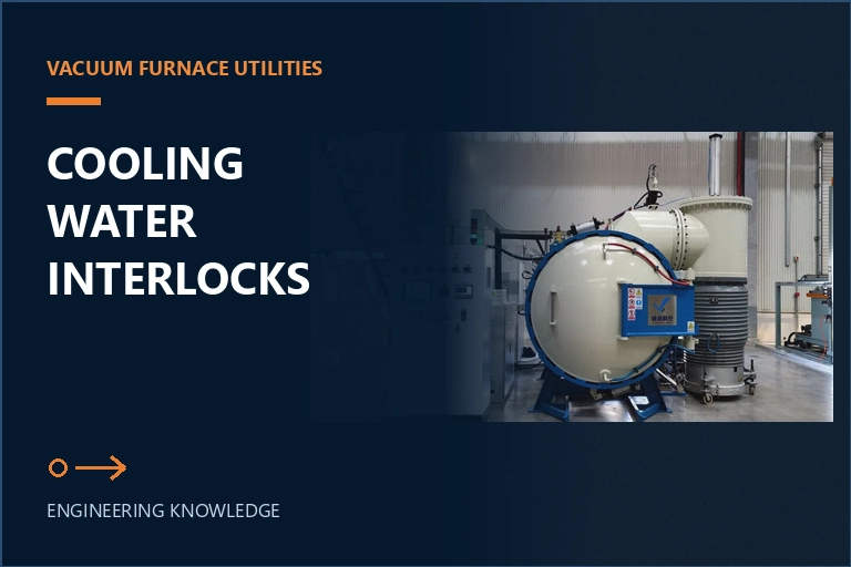
A vacuum furnace cooling water system should be accepted as a monitored protection function, not as a pipe connection that merely produces flow. Define the heat-removal duty and protected branches, verify supply and return conditions at the furnace, prove sensor and valve behavior, challenge every alarm and trip with safe simulated faults, and retain evidence that links each response to the approved control logic.
Define what the cooling-water system must protect
Start with a thermal and equipment inventory rather than a single plant-water connection size. Identify every component that depends on cooling during heating, vacuum operation, gas quenching, controlled cooling, standby and an abnormal shutdown. Depending on the delivered furnace, the protected inventory may include the vessel or door, seals, electrode and thermocouple feedthroughs, diffusion or mechanical pumping equipment, high-pressure gas-circulation hardware, heat exchangers, motors, power components and auxiliary piping. The approved equipment drawings and technical agreement must define the actual branches.
Record which branch removes process heat and which branch protects a temperature-sensitive boundary. A branch that keeps a seal or electrical feedthrough within its allowable condition may require protection even when its heat load is smaller than the main exchanger. Conversely, the gas-cooling heat exchanger can impose a high, cycle-dependent duty that is not represented by idle flow. Acceptance must therefore cover each operating mode, including the transition from vacuum heating to high-pressure circulation and the period after a protective stop.
For every branch, document the source, isolation points, flow direction, normal valve position, instrument location, required operating window, alarm response, trip response and safe residual-cooling requirement. Mark whether a manual bypass exists and how it is controlled. This branch register prevents a healthy common header from hiding one blocked or air-bound path and gives commissioning teams a consistent reference for drawings, software tags, physical labels and test records.
Map the loop and measure conditions at the furnace
Measure the conditions delivered to the furnace, not only the nominal capability of the central cooling plant. Long pipe runs, undersized valves, strainers, elevation, parallel users and fouling can change pressure and flow between the utility source and the machine. Record supply temperature and pressure, return temperature and pressure, branch flow where required, and the differential conditions that reveal whether heat is being removed. Use calibrated instruments and record where each value was taken.
The loop should make flow paths and sensor coverage unambiguous. A common supply can feed multiple protected branches, but each critical branch needs a method of proving that its required condition exists. Return temperature adds useful evidence because a flow indication alone cannot show whether the measurement represents the intended circuit. Where the furnace control relies on a switch or transmitter, compare the displayed or recorded value with an independent reference during commissioning.
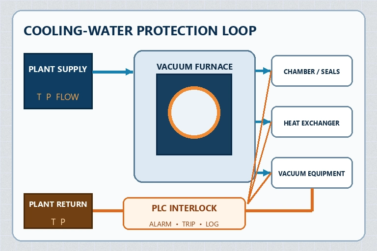
Check flow direction, trapped-air points, drainability, hose or flexible-connection routing and accessibility for cleaning. Confirm that valves cannot be left in a hidden unsafe position after maintenance. If the plant uses a closed circuit or a water-to-water exchanger, define which side owns pressure stability, water quality and freeze protection. The furnace supplier and plant utility owner should agree on the battery limits so a future alarm is not delayed by uncertainty about responsibility.
Set an operating envelope for every relevant mode
Convert supplier requirements and plant capability into an approved operating envelope. Define the variables that matter at the furnace boundary: supply temperature, available pressure, branch flow or differential pressure, allowable return condition, water quality limits when specified, and the maximum credible utility variation. Do not copy a value from another furnace. The required range depends on the delivered exchanger, protected components, duty cycle, load, gas-cooling configuration and site installation.
Review the envelope under idle, heating, pump-down, high-pressure cooling, controlled cooldown and post-trip conditions. A utility system that is stable at idle may sag when the furnace heat exchanger and other plant users demand flow together. Capture the worst representative production condition and the expected seasonal condition. If the plant cannot reproduce the design maximum during site acceptance, document how the remaining condition will be demonstrated before production release.
| Acceptance surface | Evidence to retain | Risk controlled |
|---|---|---|
| Utility boundary | Supply and return temperature, pressure, connection and available flow | A plant header that cannot support the specified duty |
| Critical branch | Flow direction, valve position, sensor response and differential condition | One blocked path hidden by healthy common flow |
| Peak process mode | Representative load, gas-cooling state, temperatures and trend record | Idle acceptance that misses the maximum heat-removal demand |
| Protective response | Alarm, trip, residual cooling, event log and reset behavior | A detected fault that does not lead to a safe machine state |
Define normal, warning and protective thresholds as separate concepts. The warning point should support operator response without masking a deteriorating branch; the trip point should protect the furnace and load according to the approved hazard and control review. Include sensor accuracy and expected process variation when setting thresholds. A narrow gap between normal operation and trip may create nuisance stops, while a wide gap can delay protection.
Challenge alarms, trips and recovery logic safely
Commissioning must prove the complete chain from a physical condition through the field device, input channel, control program, operator display and final protective action. A screen tag that changes state is not sufficient. Use an approved test method to simulate or create a low-flow, high-temperature, abnormal-pressure, sensor-failure or communication condition without exposing personnel or equipment to an uncontrolled hazard. Record the initial state, stimulus, detected value, alarm text, response time, commanded action and final machine state.
Test the logic in the modes where it matters. A branch-loss input may require a different response during standby, heating and high-pressure gas circulation. Verify what happens to heaters, pumps, valves, fans, pressure control and recipe execution. Confirm whether residual cooling continues after the heat source is removed and how long the protection remains active. The approved design should define which actions are automatic and which require an operator.
Challenge failure modes as well as process limits. Disconnect or otherwise simulate a failed sensor using the authorized test procedure; confirm that an implausible or missing signal does not appear as a healthy condition. Check power restoration, control restart and event retention. A reset should not silently resume a cycle when the underlying water condition remains outside its permitted range. Require deliberate acknowledgement and the defined recovery checks before production can continue.
Coordinate these tests with electrical and mechanical safe-work procedures. Cooling-water isolation, electrical energy, stored gas pressure, hot surfaces and automatic motion can exist together. Apply the site control-of-hazardous-energy procedure and the supplier's instructions; do not improvise a live fault test simply to complete a checklist. The goal is reproducible evidence of safe logic, not a dramatic demonstration.
Control water quality, cleanliness and post-acceptance change
Stable heat removal also depends on the condition of the circuit. Define the applicable water-quality, filtration, corrosion-control and cleaning requirements from the furnace and utility-system documentation. Review material compatibility across the furnace, exchanger, hoses, seals and plant piping. Avoid introducing an unapproved chemical treatment or mixed-metal condition that may protect one part of the plant while attacking another.
Establish a baseline for strainers, filters, exchanger performance, branch flow, supply and return temperatures, pressure differential, leakage and instrument readings. Trend comparable process states rather than mixing idle and peak-cooling values. A gradual change in differential pressure or return temperature can justify inspection before an interlock occurs. Retain maintenance and calibration records so an unexplained process shift can be compared with utility work.
Define review or reacceptance triggers. Examples include a different central chiller or cooling tower arrangement, changed treatment chemistry, modified pipe size, relocated furnace, new parallel users, exchanger service, replaced sensors, revised alarm thresholds, control-software changes or a branch that was opened for repair. The exact retest depends on the change, but the decision should be documented before the furnace returns to production.
Match the furnace and utility scope before purchase
SYNHTE's Vacuum Heat Treatment Furnace range includes the Vacuum Gas Quenching Furnace. The current product page describes high-pressure inert-gas cooling, a circulation fan, gas-flow distribution and a heat-exchanger cooling system. Those functions make the plant cooling-water interface part of the complete process configuration rather than a late installation detail.
Share the alloy and load, usable work zone, batch mass, gas type and pressure, expected cycle frequency, facility water source, seasonal supply range, available pressure and flow, pipe route, treatment method, ambient conditions, monitoring standard and acceptance requirements. Ask which furnace branches require continuous cooling, what evidence is available at factory acceptance, what must be repeated after installation and how the controls respond when a critical condition is lost.
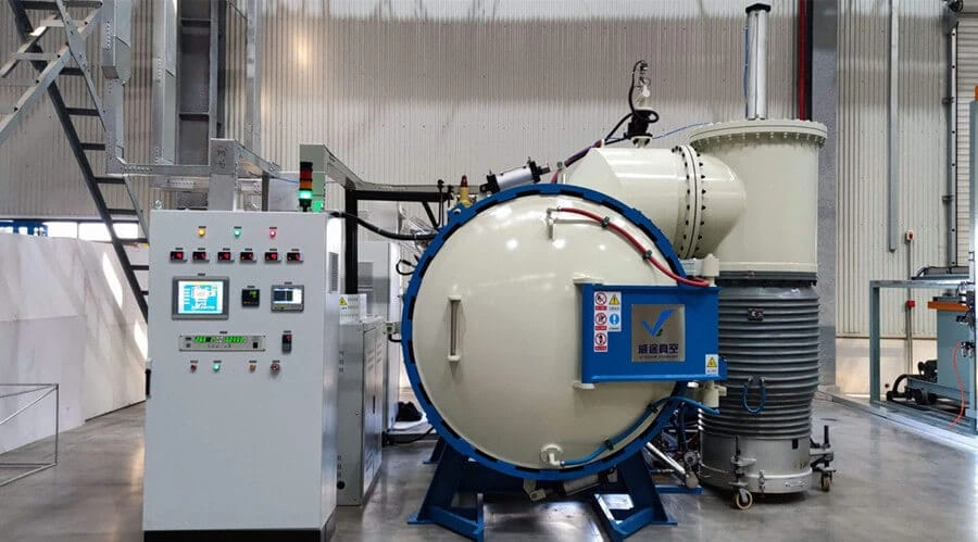
Put deliverables into the technical agreement: branch drawing, connection schedule, design assumptions, instrument list, cause-and-effect matrix, alarm and trip texts, test methods, calibration evidence, trend records, spare parts and maintenance access. If a representative production load is not available for factory testing, agree on the substitute duty and the site test that will close the gap. A clear boundary between supplier and plant responsibilities reduces commissioning delay and gives operations a usable protection baseline.
Vacuum Gas Quenching Furnace
The vacuum gas-quenching platform combines vacuum heating, high-pressure gas circulation and a heat-exchanger cooling system. Its cooling-water scope must be selected and accepted together with the actual load, cooling pressure, gas-flow hardware, facility conditions and protection logic.
What to include in your enquiry
- Exact material, incoming condition and governing drawing or specification
- Part, interface, fixture, stack and production-load drawings
- Required process outcome, acceptance methods, limits and sample locations
- Current process route, fixed variables, development questions and known risks
- Batch volume, data-retention needs, utilities, site interfaces and delivery requirements