
Continuous Vacuum Brazing Furnace vs Batch Furnace: Which Is Better for Mass Production
The decision between a batch vacuum brazing furnace and a continuous or indexed line should be made from qualified production data. Annual demand alone is not enough: product mix, usable load, cycle time, changeovers, contamination control, maintenance, traceability, floor space and acceptance requirements all affect the correct architecture.
Define the two production architectures first
A batch furnace processes a defined load through evacuation, heating, brazing and cooling before the chamber is opened for the next load. Batch does not mean manual: loading, recipe control, data collection and material handling can be automated.
A continuous or indexed vacuum brazing line moves production through a sequence designed for repeated flow. The physical architecture may use isolated chambers, indexed stations or another transfer arrangement. Before comparing performance, confirm what the proposed line actually includes: pressure isolation, transfer method, heating zones, cooling route, buffer capacity and response to a station fault.
The AWS furnace brazing specification focuses attention on equipment, materials, procedures and inspection. Those controls apply regardless of whether parts move by batch or line.
Batch vs continuous decision matrix
| Decision input | Batch tends to fit when | Continuous / indexed tends to fit when | Buyer evidence required |
|---|---|---|---|
| Product family | Geometry, alloy, filler or recipe changes frequently | One stable family can use repeated fixtures and recipes | Part-family list and approved process sheets |
| Annual good-part demand | Demand is variable or several products share capacity | Sustained demand can load the line at a useful rate | Good parts per year by product, not gross forecasts |
| Cycle and takt | Qualified batch cycle can meet demand with acceptable utilization | Required takt justifies staged or flowing capacity | Qualified heat profile, cooling time and target takt |
| Usable load | Fixtures can combine mixed or irregular work efficiently | Repeated fixtures have consistent density and thermal mass | Fixture drawing, part count, load mass and thermocouple study |
| Changeovers | Frequent recipes and part changes make flexibility valuable | Long campaigns limit changeover loss | Change frequency, cleaning need and release procedure |
| Contamination control | Different materials or fillers benefit from separated batches | A stable product family supports a dedicated line condition | Material/filler matrix and chamber-cleaning criteria |
| Maintenance | A chamber can be planned around independent production cells | The line has defined access, spares and recovery from station downtime | Preventive-maintenance plan, critical spares and bypass strategy |
| Traceability | Batch records naturally identify a discrete load | Part or carrier tracking follows each indexed position | Required data fields, retention and product genealogy |
| Floor space and utilities | Compact cells or shared utilities fit the plant | Line length, buffers and dedicated utilities are available | Layout, power, water, gas, exhaust and material-flow study |
| Growth plan | Additional batch cells can add modular capacity | A dedicated line supports a stable high-volume program | Volume scenarios and expansion constraints |
Calculate cost per accepted part
Do not compare only furnace purchase price or nameplate throughput. A useful model includes capital recovery, energy and utilities, labor, fixtures, consumables, planned maintenance, downtime, changeovers, scrap, rework and the number of accepted parts delivered.
A continuous line can lose its theoretical advantage when product campaigns are short, changeovers are frequent or one station constrains availability. A batch system can lose its flexibility advantage when loading is inefficient, cycles are underfilled or manual handling limits takt. Run the model with at least expected, low-demand and high-demand scenarios.
Qualify the process and the equipment
The selected architecture must reproduce the accepted joint, not merely hit a furnace temperature. Define the base material and filler, joint design, surface preparation, fixture, load arrangement, vacuum trend, temperature distribution, cooling route and inspection method. ISO 18279:2023 classifies brazed-joint imperfections, while the applicable drawing or procedure must define what is acceptable for the component.
For aluminum assemblies, use the applicable requirements in AWS C3.7M/C3.7:2011 (R2022). For other furnace-brazed alloys, review the relevant furnace brazing specification and customer requirements. FAT and SAT should verify the agreed equipment functions, temperature evidence, vacuum performance, records, safety interlocks and representative load result.
Joint design and fixture restraint can dominate the result in either architecture. Review the vacuum brazing joint clearance and fixturing guide before freezing the equipment specification.
Choose the right next step
Use this comparison to select the production architecture, then continue with the equipment route that fits your project. For a broad equipment-family review, explore the vacuum brazing furnace range. Repetitive flow-production projects can review the continuous vacuum brazing furnace, while aluminum batch applications can start with the high-vacuum aluminum brazing furnace.
SYNHTE can compare a batch chamber with a continuous or indexed line only after the real production case is defined. The useful starting point is a part-family and capacity study that includes fixture density, qualified cycle time, product changes, maintenance access and acceptance tests.
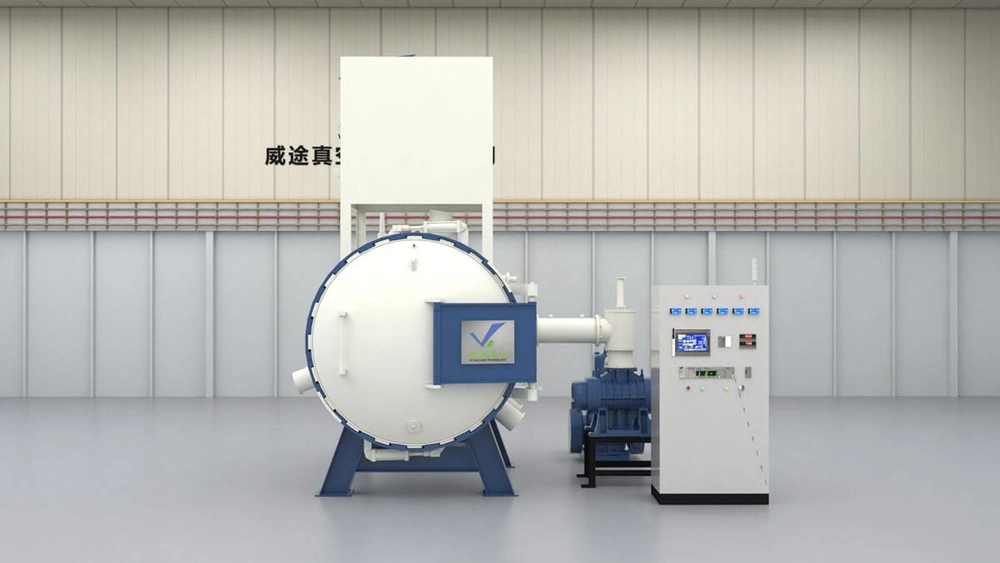
Vacuum Brazing Furnace Systems
Start with the material, filler, load, process temperature, vacuum requirement and production model. The equipment family page provides the route to batch, continuous and application-specific brazing configurations.
- Batch and line architectures reviewed against actual demand
- Material, filler, fixture and load matched to the hot zone
- FAT/SAT and traceability inputs defined before final configuration
What to include in your enquiry
- Part drawings, base material, filler and joint/fixture concept
- Annual good-part demand, target takt and expected product mix
- Qualified cycle time, usable batch size and fixture density
- Product-change frequency and contamination-control requirements
- Available floor space, utilities and material-flow constraints
- Inspection, traceability, FAT and SAT acceptance criteria
Compare the two routes with your production data
Send the drawings, material and filler, annual volume, target takt, batch size, change frequency, available space and acceptance criteria. SYNHTE can compare a batch furnace with a continuous or indexed line for the application.
Send the production inputs