
SYNHTE engineering guide
Vacuum Brazing Joint Design: Clearance, Filler Placement and Fixturing Guide
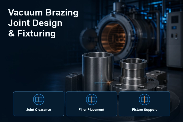
| Observed result | Likely design or preparation issue | Check first | Possible direction |
|---|---|---|---|
| Incomplete fill | Insufficient capillary path, blocked vent or poor wetting | Brazing-temperature gap, surface condition and filler location | Revise joint access and validate the gap |
| Excess filler / runout | Too much filler or an overly open flow path | Filler volume, gravity and stop-off strategy | Meter filler and control the reservoir |
| Distortion | Fixture over-constraint or uneven thermal mass | Expansion path, support points and heating balance | Locate the assembly without locking expansion |
| Porosity or trapped residue | Blind volume, contamination or volatile material | Venting, cleaning and fixture contact | Create an escape path and improve preparation |
Vacuum brazing joint design for controlled capillary action
Brazing filler flows into a close, clean joint primarily by capillary action. The correct clearance is specific to the base materials, filler family, joint geometry and thermal cycle. A gap that is too tight can stop filler entry; a gap that is too wide can reduce capillary draw, cause incomplete fill or allow filler to run away from the joint.Do not publish one clearance as a universal rule. Define a nominal range with the filler-metal supplier and prove it with representative coupon and production trials. Include variation from machining, flatness, assembly force and differential thermal expansion—not only the room-temperature drawing dimension.Put filler where it can feed the joint
Preforms, foils, paste and powder each require a different application strategy. Place filler so that it is available at the joint entrance and can be drawn through the intended path. Avoid trapping it behind a closed geometry, forcing it to bridge large unsupported gaps, or allowing it to fall into areas where excess flow creates blockage or contamination.For complex assemblies, identify vent paths for trapped air or gas. Blind cavities, enclosed channels and unvented lap joints can slow evacuation and create inconsistent results. Review the fixture and part together; a good part design can still fail when tooling hides the joint or blocks the thermal path.Fixture for position, not for restraint
A brazing fixture must locate the assembly accurately while allowing predictable thermal expansion. Overly rigid tooling can distort thin sections or force a gap open as temperature rises. Too little support allows movement, sagging or misalignment.Use fixture materials that are compatible with the temperature, vacuum environment and process chemistry. Keep contact points minimal where practical, protect critical surfaces, and avoid designs that create large thermal shadows. Trial fixtures with thermocouples or representative parts when mass and geometry are significant.Surface preparation still controls wetting
Parts must reach the furnace free of oils, oxide, fingerprints, machining residue and unapproved adhesives. Cleaning should be defined, repeatable and compatible with both base metal and filler. Store prepared parts so that they are not re-contaminated before loading.If wetting is poor, do not blame vacuum pressure first. Review joint clearance, surface condition, filler identity, filler placement, assembly sequence and the actual temperature profile. The root cause is frequently a combination of those variables.A drawing-review checklist before production
- Is the filler metal named and compatible with both base materials?
- Are nominal gap and variation defined at the brazing temperature as well as room temperature?
- Can filler feed every critical joint by capillary action?
- Are blind volumes vented and are drainage/overflow paths acceptable?
- Does the fixture preserve alignment without preventing thermal movement?
- Are inspection points and leak-test requirements stated?
Recommended equipment
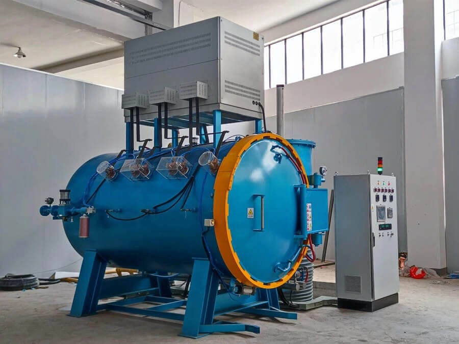
High-Temperature Vacuum Brazing Furnace
A joint design can only be validated inside a controlled thermal and vacuum process. For high-temperature brazing projects, match usable work zone, load arrangement, temperature uniformity, vacuum performance and cooling strategy to the assembly—not only to the filler liquidus.- Uniform heating across the assembly
- Vacuum performance for clean wetting
- Recorded repeatable thermal cycles
What to include in your enquiry
These details let the engineering team respond with a relevant configuration instead of a generic catalogue answer:- Base materials, filler alloy and service environment
- Joint drawing with nominal and tolerance dimensions
- Assembly orientation, filler form and placement
- Fixture material, contact points and expected expansion
- Acceptance test, leak rate or strength requirement