
Vacuum Furnace Leak-Rate Testing: Rate-of-Rise and Helium Leak Detection
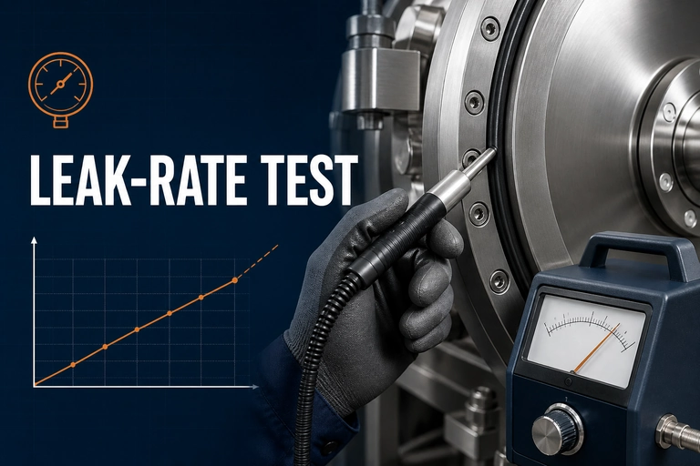
Vacuum furnace leak rate testing combines a controlled rate-of-rise measurement with targeted helium detection to separate a verified external leak from outgassing, moisture or a measurement issue. Use the same documented test condition before deciding on a repair.
Vacuum Furnace Leak Rate Testing: First Checks
Quick answer
A useful leak test first separates a real external leak from normal outgassing, residual moisture, process contamination or a measurement problem. A controlled rate-of-rise test quantifies how fast pressure increases in an isolated, clean and stable furnace; helium leak detection is then used to locate a confirmed external leak. The test condition and acceptance criterion must follow the furnace design and qualified process.
Vacuum furnace leak rate testing: why it matters
A vacuum furnace can reach a low displayed pressure yet still be unsuitable for a sensitive brazing, heat-treatment or sintering cycle. Leaks and gas release from the load, fixtures, insulation or chamber surfaces introduce reactive species and extend pump-down time. The result may be inconsistent filler flow, surface discoloration, variable heat treatment response, carbon or oxygen-related process risk, or an avoidable production delay.
The first question is not “where is the leak?” It is “what changed, under which repeatable test condition?” Compare the same chamber condition, pump configuration, gauge location and measurement interval. A test immediately after opening a damp chamber does not mean the same thing as a test after the furnace has been cleaned, dried and stabilized.
What a rate-of-rise test shows
For a rate-of-rise test, the chamber is evacuated under a defined clean, dry and empty—or otherwise specified—condition. Once the required starting condition is reached, the chamber is isolated from the pumping system and pressure is recorded for a defined interval. The pressure rise over time gives an operational measure that can be trended against the same furnace and the approved limit for the process.
| Observation | What it can indicate | Next check |
|---|---|---|
| Repeatable pressure rise in a controlled empty test | External leak, internal valve leakage, or a stable gas source | Verify isolation and continue to targeted leak detection |
| Rate improves as the chamber and load dry out | Moisture or process outgassing may dominate | Review cleaning, bake-out, load condition and maintenance history |
| Different results at different gauge locations | Gauge, line conductance or local valve issue | Cross-check gauges and confirm the test configuration |
| Only loaded cycles are affected | Load, fixture, binder, oil or trapped volume may be contributing | Test representative materials separately and review loading practice |
When helium leak detection is appropriate
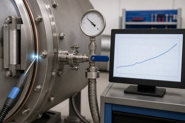
Helium leak detection is a location method, not a substitute for defining the problem. After a repeatable test confirms abnormal behaviour, trained personnel can connect the correct detector arrangement and expose suspected seals, doors, feedthroughs, valve stems, joints and service interfaces to a controlled helium source. A detector response helps narrow the fault to a physical path.
Keep the test disciplined. Avoid introducing unnecessary oils, sprays or contaminants into a clean system. Record the test state, components checked and repairs made, then repeat the same rate-of-rise test. A repair is only verified when the original symptom has been removed under the same comparison condition.
A practical diagnostic sequence
A disciplined sequence helps separate pressure-rise behaviour, suspected leak paths and the confirmation step before production resumes.
- Confirm that the gauge, unit, logging interval and starting condition are valid.
- Repeat a controlled rate-of-rise test with the furnace in the approved diagnostic condition.
- Compare the result with previous verified tests, not with a generic number from another furnace.
- Separate chamber, valve, pump-line and load-related possibilities by controlled isolation.
- Use helium detection or other approved methods only after the fault path has been narrowed.
- Document the repair and repeat the original acceptance test before returning to qualified production.
For the broader symptom tree, see Vacuum Furnace High Base Pressure Troubleshooting. Planned checks for seals, pumps, cooling utilities and hot-zone condition belong in the Vacuum Furnace Preventive Maintenance Checklist.
For first-pass equipment selection, use Vacuum Furnace Systems to compare architectures and the Vacuum Heat Treatment Furnace system family to frame the process requirements. When the production route includes controlled gas quenching, review the Vacuum Gas Quenching Furnace to put chamber integrity, evacuation recovery and load conditions into the equipment brief.
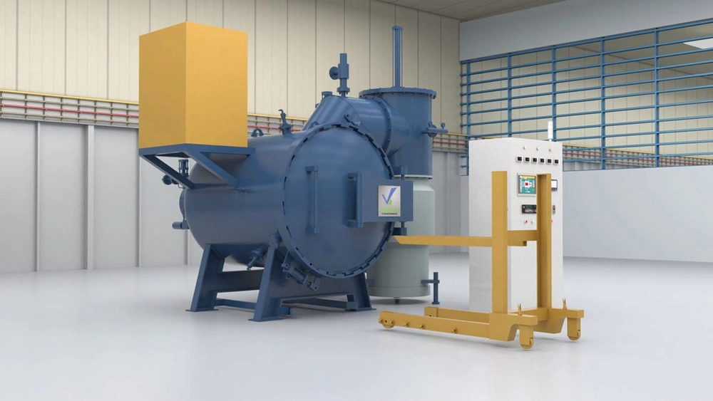
Vacuum Heat Treatment Furnace
A process-led configuration can combine the chamber size, vacuum system, controls, gas cooling and data capture needed for the actual material and qualification requirements.
- Maintainable vacuum-system layout
- Process and equipment data recording
- Configuration matched to load and cooling requirements
What to include in your enquiry
To discuss a leak-rate issue or a new system specification, share the process context rather than only a final pressure value.
- Furnace type, chamber size and vacuum-pump configuration
- Current test condition, starting pressure, time interval and gauge location
- Material, fixtures and any binder, oil or moisture sources in the load
- Required process pressure, cycle time and qualification evidence
- Recent maintenance, repairs or changes in the affected trend
Technical references
- ASTM E498/E498M — Tracer-Probe Leak Testing — official ASTM practice for locating and evaluating leaks with mass-spectrometer or residual-gas-analyzer tracer-probe methods.
- ASTM E432 — Guide for Selection of a Leak Testing Method — official ASTM leak-testing standards listing that identifies the method-selection guide and supporting practices.