Diffusion Bonding Surface Preparation: Interface Cleanliness and Assembly Control
Diffusion bonding surface preparation should create a defined, repeatable interface and preserve it until load is applied. Specify the material and interface function, control flatness and finish with an appropriate measurement method, use a material-compatible cleaning route, prevent recontamination and excessive exposure, assemble with traceable orientation and tooling, and qualify the prepared interface with position-based joint evidence. Vacuum does not repair oil, particles, uncontrolled oxide or poor fit left at assembly.
Define the material pair and interface function first
Begin with the exact materials, product forms and condition at the interface. Record alloy or grade, heat or lot, heat-treatment condition, coating or plating, manufacturing route and any interlayer that is part of the approved design. Similar and dissimilar combinations can form different oxides, reaction products and diffusion zones, so a cleaning route qualified for one pair should not be transferred to another by appearance alone.
Define what the interface must do in service. The bonded area may carry structural load, seal a fluid passage, conduct heat or electricity, preserve a channel geometry or support a later manufacturing step. That function determines which surfaces are critical, where samples should be taken and which acceptance methods matter. A smooth external edge is not proof of an acceptable internal interface in a large plate stack or channelled assembly.
Separate drawing requirements from process-development variables. Flatness, parallelism, interface area, allowed deformation, final dimensions and inspection access should be controlled by the product definition. Surface finish, cleaning sequence, protected holding time, assembly environment, interlayer preparation and tooling contact may begin as development variables but must become controlled instructions before production release.
Do not prescribe one universal roughness or cleaning chemistry in a general article. Research shows that surface roughness, oxide behavior and bonding response interact with alloy, atmosphere, temperature, pressure and deformation. A finish that increases useful contact in one material system can trap voids or require different pressure in another. Use material-specific trials and joint evidence to establish the working window.
Control flatness, waviness and surface finish as separate variables
Surface roughness does not describe the whole contact condition. Measure the geometry that matters at the interface: overall flatness, local waviness, edge roll-off, machining lay, scratches, pits, burrs and the relationship between mating parts. Two surfaces can share a similar average roughness value while touching at very different locations. Record the measurement method, sampling area, direction, instrument and acceptance rule with the part drawing or preparation instruction.
Review how the chosen finish interacts with the available pressure and allowed deformation. Initial contact occurs at asperities; heat and force then increase real contact and support diffusion and void closure. If the surface is too irregular for the qualified pressure, unclosed regions can remain. If preparation removes too much stock or rounds critical edges, geometry can move outside the assembly requirement before bonding begins.
Control the complete machining and finishing sequence. Identify the abrasive, tool, direction, coolant or lubricant, final pass, cleaning transition and inspection point. Prevent embedded grit, smeared material, transferred tool metal and deep directional damage. NASA technical guidance on diffusion-bonded aerospace structures specifically warns that grit, oils, metal compounds and oxides can compromise the surface and contribute to voids or incomplete bonding.
Handle rework as a defined route. Re-polishing one part can change thickness, flatness or stack height and may require the mating surface to be reviewed again. Set limits for the number or amount of rework, require a final geometry check and preserve part identity. Do not allow an operator to remove a visible mark until the surface looks bright without knowing how much material was removed.
Clean, protect and assemble the interface as one sequence
Write the cleaning route for the actual material and prior manufacturing residues. Identify the approved cleaner or process, concentration or operating condition when applicable, rinsing, drying, tool and container controls, inspection and waste or safety requirements. Confirm compatibility with the base material, coating and interlayer. Avoid substituting a solvent or abrasive because it is available at the workstation.
Inspect after the final preparation step, not before it. Depending on the process, evidence may include controlled visual inspection, water-break or cleanliness checks, particle control, contact-angle or surface-analysis work during development, roughness and flatness measurement, retained witness samples or another material-appropriate method. Define what the method can prove. A visually bright surface can still carry a thin film, and a laboratory surface analysis may not represent every production part unless sampling and handling are controlled.
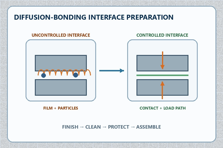
Control time and environment between final cleaning and assembly. Record the maximum qualified exposure, storage container, clean cover or packaging, workstation condition, gloves or handling tools and the event that starts the clock. Sensitive materials can form new surface films quickly, while any material can collect dust, fingerprints, oil mist or packaging residue. If the limit is exceeded or the cover is opened in an uncontrolled area, use the defined reinspection or recleaning route.
Assemble with traceable orientation and minimum handling. Mark non-interface surfaces where practical, identify mating part numbers and faces, preserve the intended lay direction or alignment, and prevent sliding that can scratch or transfer debris across the prepared area. When an interlayer is used, control its identity, thickness, condition, location and protected handling. The qualified interface is the assembled stack entering the furnace, not an isolated coupon immediately after cleaning.
Coordinate prepared surfaces with tooling, interlayers and vacuum
A clean interface can still fail to make useful contact when the tooling stack is not flat, parallel or stable. Map the load path from the press structure through platens, tools, interlayers and the workpiece. Record contact areas, stack height, locating features, restraint, allowed motion and thermal expansion. The diffusion bonding pressure-uniformity guide explains how tooling and position-based evidence extend this surface-preparation plan.
Protect prepared faces during fixturing. Avoid contact with dirty clamps, bench surfaces, lifting devices or temporary markers. If sliding is unavoidable, qualify the motion and inspect the surface afterward. Use clean tooling and define which tool faces require their own preparation. A particle transferred from a platen, shim or spacer can enter the interface even when both parts passed cleaning.
When an interlayer, coating or foil is required, treat it as part of the interface system. Control material identity, thickness, surface condition, storage, cutting method, burrs, cleanliness, orientation and coverage. Confirm the intended metallurgical role and the final acceptance route. Do not add a soft layer simply to compensate for poor flatness; it can change chemistry, diffusion behavior, deformation and service performance.
Vacuum or a controlled atmosphere limits reactions during heating, but it is not a substitute for preparation. Pump-down may remove some adsorbed species and the thermal cycle can change certain oxides, yet stable films, oil, particles and trapped contamination can remain or outgas into the chamber. Separate a high-base-pressure or pump-down deviation from an interface-control deviation, and investigate both when the process record supports it.
Qualify interface evidence by position and function
Build the qualification plan from the bonded part and its failure risk. Identify center, edge, corner, channel, thick, thin, highly restrained and difficult-to-inspect regions that may experience different contact or thermal conditions. Preserve position identity from the prepared stack through sectioning or nondestructive examination. A strong specimen removed from one favorable location does not prove the whole interface.
Select methods that answer the interface function. Depending on material and geometry, evidence may include dimensional inspection, leak testing, ultrasonic or other nondestructive examination, metallographic sections, interface coverage, microstructure, hardness, tensile or shear testing, electrical or thermal performance and process-record review. Define the method, specimen preparation, sample location, acceptance limit and product-disposition rule before the qualification run.
| Control surface | Evidence to retain | Release question |
|---|---|---|
| Material and finish | Material identity, drawing face, flatness, finish method and measurement record | Was the intended interface geometry prepared? |
| Cleaning and exposure | Approved route, inspection, completion time, protected storage and assembly time | Was the prepared state preserved to assembly? |
| Tooling and process | Stack drawing, tooling identity, load path, temperature, force, displacement and vacuum record | Did the furnace cycle act on the qualified interface? |
| Bonded result | Position-labelled examination, dimensions and functional or mechanical results | Did the interface meet its defined service requirement? |
Use witness samples only when they represent the critical variables. A separate coupon may support destructive testing, but it should match material, preparation, exposure, pressure path and thermal position closely enough for its purpose. Record its relation to the production part and do not let convenient coupon results replace examination of the actual assembly when the drawing requires it.
Retain negative evidence during development. Record unbonded areas, inclusions, excessive deformation, surface reaction and location, then compare them with the preparation and process history. This establishes which controls matter and prevents the successful trial from becoming an undocumented recipe. The goal is a defensible interface window, not one visually impressive section.
Diagnose interface findings before changing the recipe
When an interface finding appears, preserve the part, location and original records before cleaning up the documentation or adjusting temperature, time or force. Compare material and part identity, machining and finish records, cleaning batch, protected exposure, assembly order, interlayer, tooling stack, load position, vacuum response, temperature, force, displacement and inspection preparation. Multiple deviations can create a similar unbonded or contaminated appearance.
Use the location and morphology to structure the investigation. Edge-only findings can point toward geometry, exposure, restraint or section-preparation effects that differ from random particle inclusions or a broad unbonded region. A repeated orientation can implicate handling, lay direction, tooling or thermal position. These patterns guide confirmation work, but final cause should be supported by material-appropriate examination rather than appearance alone.
Set engineering-review or requalification triggers for a material grade or condition change, new supplier route, coating or interlayer change, revised machining or abrasive method, cleaner or rinse change, measurement-method change, extended exposure, new packaging, tooling repair, platen work, changed stack height or interface area, furnace or hot-zone change, vacuum-system maintenance, recipe revision or acceptance-method change. Define whether the response is document review, confirmation samples or full requalification.
Trend preparation and result variables together. Surface measurement, cleaning completion, exposure time, assembly operator, tooling identity, furnace cycle and position-based interface results can reveal drift. Use the trend to focus audits and confirmation work, not to relax drawing requirements. A stable average can still hide a repeated edge or orientation problem if position identity is lost.
Match the equipment to the interface-control plan
SYNHTE's Vacuum Brazing and Diffusion Bonding Systems include the VTM Vacuum Diffusion Bonding and Brazing Furnace for projects that coordinate temperature, axial force, vacuum, tooling and process records. The current product page describes configurable hot-zone, press, displacement, chamber and control functions. Final equipment selection should follow the real material pair, interface area, tooling stack, working envelope, pressure and deformation needs, vacuum or atmosphere plan, inspection access and production evidence.
Share material certificates and product condition, interface and part drawings, flatness and finish requirements, preparation and cleaning proposal, maximum protected exposure, interlayer details, stack and tooling drawings, contact area, temperature and force history, displacement needs, vacuum or gas basis, sample positions, inspection methods, acceptance limits, throughput and site utilities. When the work is primarily pressure sintering inside a die rather than bonding a defined assembly interface, compare the VMPE Vacuum Hot Press Furnace instead of assuming the same tooling architecture applies.
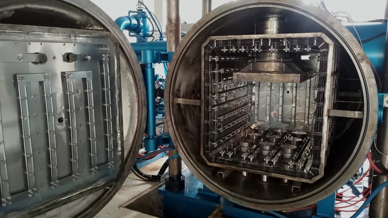
VTM Vacuum Diffusion Bonding and Brazing Furnace
SYNHTE VTM diffusion-bonding systems coordinate a vacuum hot zone, axial force, displacement monitoring, tooling space and project-specific controls around the assembly. Surface preparation must be reviewed with material chemistry, interface area, platen and tooling contact, process atmosphere, loading sequence and the evidence required to release the bonded part.
What to include in your enquiry
- Exact material, incoming condition and governing drawing or specification
- Part, interface, fixture, stack and production-load drawings
- Required process outcome, acceptance methods, limits and sample locations
- Current process route, fixed variables, development questions and known risks
- Batch volume, data-retention needs, utilities, site interfaces and delivery requirements