
Diffusion Bonding Pressure Uniformity: Tooling, Parallelism and Qualification Evidence
Diffusion bonding pressure uniformity cannot be proven from hydraulic force alone. It must be qualified as a complete load path that includes interface flatness and cleanliness, stack geometry, tool stiffness, platen parallelism, thermal expansion, pressure timing and position-based inspection. A release plan should connect every bonded location to the tooling setup, cycle record and acceptance evidence that represents it.
Define the bond requirement and complete load path
Begin with the bonded assembly, not the maximum tonnage shown on a furnace specification. Record the base materials, product form, interface area, number of layers, joint function, allowable deformation, dimensional limits, service environment, inspection access and the governing drawing or material procedure. A flat plate stack, a laminated cooling structure and a shaped aerospace assembly do not transfer pressure in the same way. The qualification must represent the geometry that will enter production.
Map the complete load path from the hydraulic system through the upper press structure, platen, tooling, workpiece stack, lower tooling and return structure. Each transition can introduce compliance, local bending or contact loss. Nominal force divided by nominal area is only a planning value; it does not prove that every interface receives the same contact condition. Tool shoulders, spacer height, edge restraint, stop-off layers, interlayers and fixture clearances can redistribute load as the assembly heats.
Define controlled variables before the first qualification run. These normally include surface preparation, maximum time from final cleaning to assembly, stack order, interface orientation, tool material, platen and tool condition, fastener or restraint method, load position, thermal-program revision, pressure application point, hold logic, cooling sequence and inspection plan. This baseline prevents a favorable result from becoming an undocumented recipe and gives engineering a clear basis for reviewing later changes.
Understand why pressure uniformity is a stack problem
Uniform hydraulic output can still produce a nonuniform interface. Platen parallelism, tool flatness, stack thickness and part waviness determine where contact begins. As temperature rises, differences in thermal expansion, stiffness and constraint can change the contact pattern. A high point may carry load early while a low region remains open; a thin tool may bend around a stiff feature; an edge restraint may prevent the stack from settling as intended. The risk increases when the bonded area is large or when internal channels reduce local support.
Use measured geometry to establish the starting condition. Check the surfaces that transfer pressure, not only the external frame. Record platen and tool condition, parallelism, flatness, thickness distribution and any planned compliant or sacrificial layer. If shims, interlayers or stop-off materials are part of the approved route, control their material, thickness, placement and lot. Avoid using an unspecified soft layer simply to hide a contact problem; it can alter chemistry, deformation or thermal response.
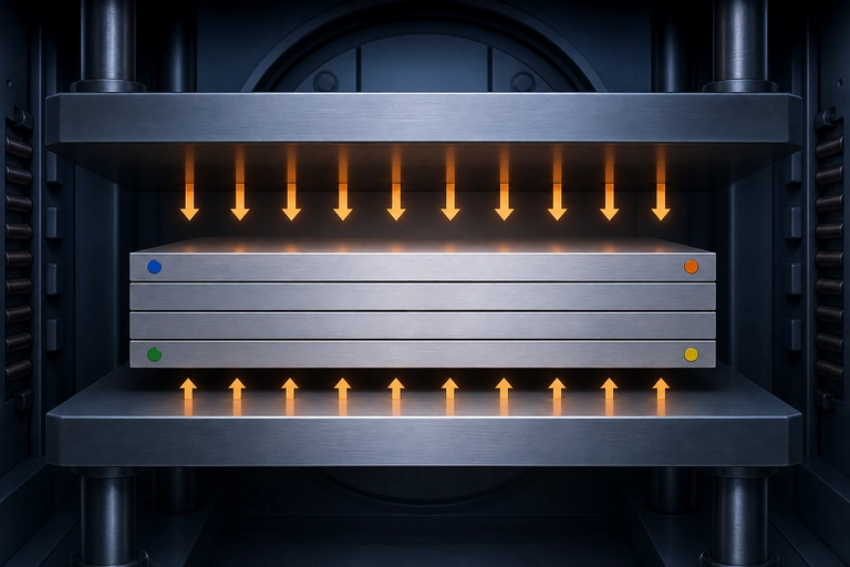
Pressure mapping or witness evidence can help during development when the chosen method remains meaningful under the relevant loading conditions. The production qualification should then connect that development evidence to measurable tooling geometry, machine records and bonded results. Do not treat a room-temperature contact check as proof of high-temperature behavior. Its purpose is to expose gross contact or setup problems before the furnace cycle, while the final qualification still depends on the actual material, thermal history and joint evidence.
Build a repeatable tooling and load-position map
A tooling drawing should identify every pressure-transfer surface, spacer, stop, support and assembly orientation. Add dimensions and inspection points that can be checked before loading. Assign a unique fixture or tooling identity and record maintenance or resurfacing history. When multiple tools are intended to be interchangeable, demonstrate that their geometry and stiffness stay within the approved envelope rather than assuming that matching part numbers create matching pressure conditions.
The load map should preserve position identity. Mark center, edge, corner, upper, lower or other risk-based locations relevant to the actual stack. Place representative production interfaces or deliberately designed witnesses at positions that challenge the usable area. If the assembly contains internal channels or regions with different support, relate inspection locations to those features. A single coupon beside the production stack may confirm furnace exposure, but it cannot prove pressure transfer inside a geometry that it does not reproduce.
| Control surface | Evidence to retain | Risk addressed |
|---|---|---|
| Platen and tool geometry | Flatness, parallelism, thickness, condition and tool identity | Early point contact or local load concentration |
| Assembly stack | Layer order, interface area, restraint, interlayer and orientation | Uncontrolled compliance or blocked settlement |
| Load position | Center, edge and feature-based position map | A favorable average hiding a weak location |
| Cycle execution | Vacuum, temperature, pressure timing, hold, alarms and cooling | A result that cannot be reproduced or investigated |
Define setup acceptance before each run. The operator should know which surfaces must be clean, which dimensions or alignment checks are required, how the stack is centered, what confirms free movement and when the assembly requires a documented engineering decision. Photographing the loaded setup can support traceability, but the image should supplement measured records rather than replace them.
Qualify the thermal-pressure sequence and recorded evidence
Diffusion bonding depends on a coordinated material-specific relationship among surface condition, temperature, pressure and time. The approved values must come from the material procedure, development work and governing acceptance requirements. Do not publish one temperature or pressure as a universal recipe. Instead, define which process variables are setpoints, which are monitored responses, how pressure is introduced relative to the thermal cycle and which deviations require containment or requalification.
Record the furnace and hot-zone identity, vacuum history, temperature-program execution, relevant load-sensor data when required, hydraulic command and response, platen movement or displacement where available, pressure stability, alarms, interruptions and cooling route. A machine can reach the commanded force while the workpiece response remains abnormal. Unexpected displacement, pressure correction or thermal lag may indicate stack settlement, tool compliance or a setup difference that deserves review before the load is released.
Use confirmation loads that include normal production variation. The qualification envelope should define permitted assembly size, interface area, stack height, tool set, load position and part family. If more than one assembly family shares a cycle, show why the selected evidence represents the important differences in geometry, stiffness, material and inspection. Recipe security, change authorization and data retention should be settled before routine production so the qualified state cannot be changed informally.
Inspect by position and define requalification triggers
Build the inspection plan from the joint function and failure risk. Depending on the assembly, evidence may include dimensional checks, leak testing, ultrasonic or other nondestructive examination, metallographic sections, interface coverage, mechanical testing and process-record review. Define the method, acceptance limit, sampling location and disposition before the qualification run. No single generic test proves every interface, and a visually clean edge does not demonstrate complete bonding inside a large or internally channelled stack.
Keep each result tied to its physical location. Compare center, edge, corner, highly restrained and locally unsupported regions when they create different pressure or thermal risks. If destructive witnesses are used, document how their material, preparation, interface, stiffness and load path represent the production joint. Analyse both the overall result and position-based variation; an acceptable average can conceal one repeatably weak area.
Define change rules prospectively. Requalification or documented engineering review may be needed after a new base-material condition, interface coating, interlayer, surface-preparation route, stack geometry, tooling revision, resurfaced pressure surface, furnace or hot-zone change, moved load location, altered pressure timing, significant maintenance event or unexplained failure. The exact rule belongs to the applicable quality system and procedure, but it should be written before production so commercial urgency does not decide it after a change has occurred.
Match furnace capability to the pressure-uniformity plan
SYNHTE's Vacuum Brazing Furnace Systems include the VTM Vacuum Diffusion Bonding & Brazing Furnace, a pressure-assisted joining platform that coordinates vacuum, heating, hydraulic loading and controlled cooling. The current product page documents delivered platen geometry, press movement, work-zone and control information. Those equipment values are a basis for application review, not a substitute for qualification of the actual stack and interface.
Share the material specifications, assembly and interface drawings, bonded area, stack height, tool and interlayer concept, required thermal-pressure sequence, usable work-zone position, load mass, inspection methods, acceptance criteria, data requirements, production volume and site utilities. Ask the supplier to explain how platen access, tooling clearance, pressure control, vacuum response, temperature evidence and data capture support the qualification plan. If the process is still uncertain, a controlled brazing and heat-treatment service route may help define test inputs before equipment scope is frozen.
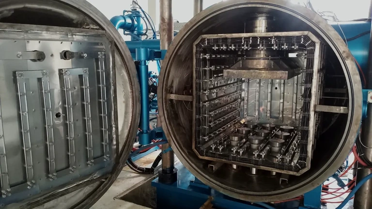
VTM Vacuum Diffusion Bonding & Brazing Furnace
The VTM platform coordinates high vacuum, controlled heating and hydraulic loading for pressure-assisted joining. Useful capability depends on the complete work-zone, platen, tooling, load and evidence plan rather than the nominal press force by itself.
What to include in your enquiry
- Exact material, incoming condition and governing drawing or specification
- Part, interface, fixture, stack and production-load drawings
- Required process outcome, acceptance methods, limits and sample locations
- Current process route, fixed variables, development questions and known risks
- Batch volume, data-retention needs, utilities, site interfaces and delivery requirements