
Binder Jet Debinding and Sintering: Qualification for Metal Parts
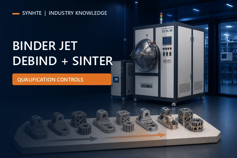
Binder jet debinding and sintering should be qualified as one connected manufacturing route, not as two independent furnace steps. Control the printed lot and green-part condition, establish a debinding window that removes the binder without damaging the fragile geometry, define a production-representative sintering load and thermal history, and release the route only after dimensional, density, material-property and position-based evidence meets the governing specification.
Connect printing, debinding and sintering in one qualification chain
Binder jetting creates a shaped powder body by selectively applying a binder. The printed component is therefore a fragile green part whose condition depends on powder characteristics, binder system, printing parameters, curing, depowdering, handling and storage. Debinding removes the temporary organic phase, while sintering consolidates the remaining powder structure. A change made before the furnace can alter what the furnace must remove, how gas leaves the part, how the geometry supports itself and how much dimensional change occurs later.
Define the qualification boundary before trials begin. Record powder and binder identification, print orientation, build position, curing or drying state, depowdering method, green dimensions, handling limits, support strategy, time to furnace, furnace identity, fixture and tray, load map, atmosphere route, thermal-program revision, cooling method and final inspection plan. The purpose is not paperwork for its own sake. It lets the team distinguish a furnace problem from a printed-lot or handling change and prevents one successful batch from becoming an undocumented production recipe.
Use risk to decide which variables must be fixed and which may operate within an approved range. Thin unsupported walls, trapped volumes, abrupt section changes, large flat surfaces and parts with asymmetric mass deserve closer attention than robust coupons. Qualification pieces should represent the actual geometry and loading challenge; simple witness bars can support material testing but cannot by themselves prove that the most fragile production feature survives the complete route.
Separate debinding risk from sintering risk
Debinding and sintering interact, but they create different failure questions. During debinding, the main concern is whether binder removal proceeds without an internal pressure build-up, residue pattern, slump, cracking, blistering or contamination event. During sintering, the questions shift to densification, shrinkage, distortion, atmosphere compatibility, grain or phase requirements when specified, and the relationship between heating, hold and cooling history. Treating every defect as a “bad sintering cycle” hides the stage where it actually began.
Build a debinding study around the real binder system and part section. Establish a controlled starting condition, document mass before and after the defined stage when meaningful, and compare representative geometries rather than relying only on a small uniform coupon. Venting and gas-removal capacity must be considered with batch mass and packing density. A route that works for a lightly loaded development tray can become unstable when a production load releases more volatile material over the same interval. Do not publish a universal heating rate or hold temperature: those values depend on the binder chemistry, powder, geometry, furnace configuration and controlling material procedure.
After debinding, define what evidence is required before the load continues or is accepted for sintering. That may include appearance, mass change, residue or carbon checks, dimensional condition, and a documented absence of damage at high-risk features. Sintering trials should then preserve the load identity and position so later density or dimensional variation can be traced back to the thermal environment rather than averaged away.
Build a production-representative load and thermal window
A production qualification load should reproduce the factors that can change heat transfer, gas removal and part support: normal batch mass, tray material, fixture contact, spacing, orientation, part-family mix, center-to-edge distribution and the locations most shielded from flow or radiation. Record the usable work-zone location rather than describing every tray as equivalent. If the production plan allows more than one load pattern, either qualify the important patterns or define a justified envelope that includes the most demanding arrangement.
Instrument and record the variables needed to explain a result. Depending on the process and quality system, this can include chamber pressure history, selected gas and pressure stages, temperature-program execution, load thermocouple data when required and practical, alarms, deviations, cooling transition, and maintenance condition. Empty-furnace capability data is useful for equipment acceptance, but production qualification must show how the actual load behaves. The approved recipe should identify which values are controlled setpoints, which are monitored responses and which deviations require review.
| Gate | Evidence to retain | Question answered |
|---|---|---|
| Printed lot | Powder, binder, build position, cure and green-part condition | Did the furnace receive a controlled starting state? |
| Debinding | Load mass, support, cycle record and agreed removal or residue checks | Was binder removed without damaging or contaminating the part? |
| Sintering | Load map, atmosphere, thermal history, cooling and deviations | Was the consolidation route repeatable across the load? |
| Acceptance | Dimensions, density, material tests and position identity | Did the production-relevant result meet the specification? |
Repeat confirmation loads with normal production variation. A capability conclusion based on one carefully arranged tray is weak because it does not reveal day-to-day input and load variation. Define recipe security, review ownership and data retention before routine release so process changes cannot bypass the evidence chain.
Measure shrinkage, density and positional variation
Shrinkage is not just one scalar percentage. Measure the dimensions that matter to function and identify direction, feature and position. A long axis, thin wall, hole spacing, flatness or interface surface may respond differently from an overall envelope dimension. Compare green and final measurements using a repeatable method, and preserve the relationship between each part and its tray location. When compensation is applied in the printed geometry, keep it tied to a qualified material, printer route, build orientation and furnace process rather than treating it as a permanent universal factor.
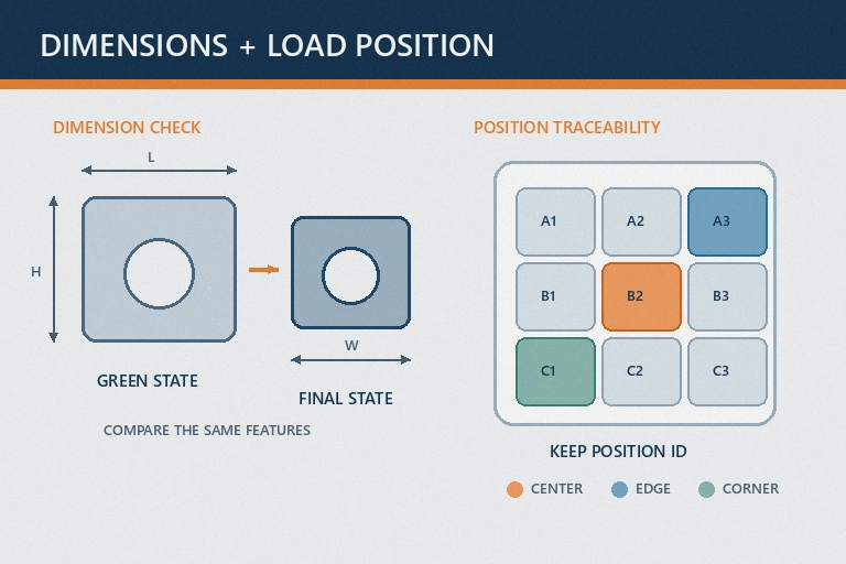
Density evidence also needs a defined method and sampling plan. Select the method required by the drawing, material specification or quality plan, then control specimen preparation and reporting. If mechanical, microstructural, chemical or nondestructive tests are required, place specimens or representative parts so they challenge relevant load regions. Do not let a favorable coupon at the easiest location release a batch whose thick or shielded production features were never examined.
Analyse averages, spread and positional bias. A stable mean can conceal an edge-to-center shift or one fixture location that repeatedly distorts parts. Trend debinding observations, final dimensions, density and other required properties against input lots, load maps and furnace records. Establish reaction rules for an outlier, an interrupted cycle, a maintenance event or a changed supply lot. The release plan should say when a result triggers containment, additional inspection, engineering review or a new qualification rather than leaving the response to operator judgment after the event.
Match the qualification plan to furnace capability
SYNHTE's Vacuum Sintering Furnace range includes an Additive Manufacturing Sintering Furnace intended for debinding, densification and high-temperature post-processing of metal additive-manufacturing parts under vacuum or a selected protective atmosphere. The current product page describes configurable graphite or molybdenum hot zones, pumping options, gas options, loading structures and debinding integration. Those choices must be matched to material compatibility, binder-removal demand, work-zone size, load mass, cleanliness, cooling and data requirements.
If the route more closely resembles metal injection molding with a defined integrated debinding and sintering system, the MIM Vacuum Debinding & Sintering Furnace provides a separate equipment context. Do not select between the two pages by keyword alone. Share the printing technology, powder and binder system, green-part size and fragility, expected volatile load, support and tray concept, required final material state, batch volume, facility gas and utilities, and the acceptance specification. Ask how the proposed configuration will record the variables in the qualification plan and how current and future load patterns fit the usable work zone.
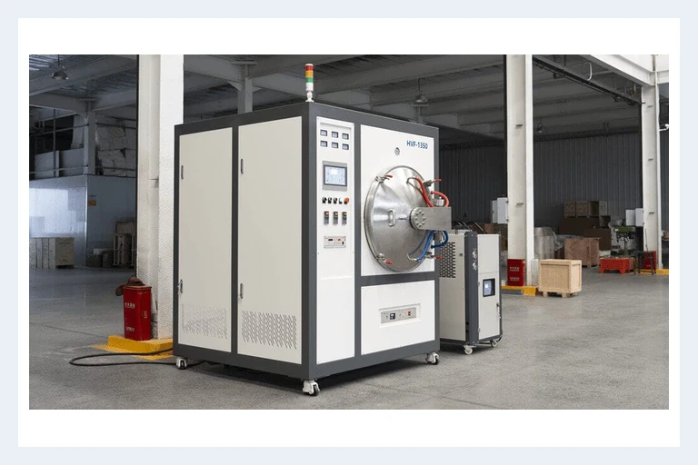
Additive Manufacturing Sintering Furnace
This furnace family supports programmable post-processing of additively manufactured metal parts under vacuum or a selected protective atmosphere, with hot-zone, pumping, gas and debinding options configured around the material and production route. Qualification remains specific to the printed feedstock, binder, geometry, load and acceptance plan.
What to include in your enquiry
- Exact material, feedstock or filler identification and governing specification
- Part, joint, fixture, tray and representative production-load drawings
- Current process route, fixed variables, development questions and known failure risks
- Required dimensions, properties, inspection methods, sampling and acceptance limits
- Expected batch volume, throughput, data-retention needs, utilities and site constraints