
Metal Injection Molding Sintering Shrinkage Control: From Feedstock to Furnace Load
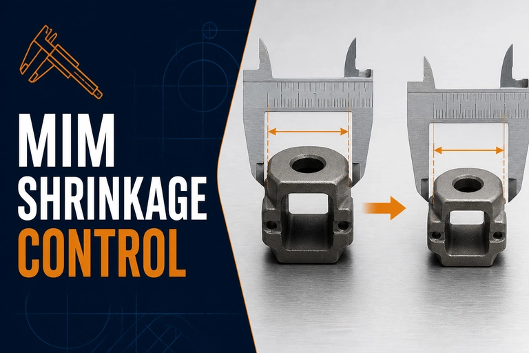
Metal injection molding sintering shrinkage is controlled across the feedstock, debinding condition, part support and furnace load rather than at one furnace setpoint alone. Track the inputs that change density development and dimensional response.
Metal Injection Molding Sintering Shrinkage: First Controls
MIM shrinkage is a controlled outcome, not a furnace-only setting. It is affected by feedstock consistency, molding, green-part geometry, debinding state, support, loading, thermal profile and sintering atmosphere or vacuum condition. A stable production process ties these variables to a qualified dimensional inspection plan.
Why shrinkage varies
During sintering, a debound compact densifies and changes dimensions. The final response can differ with powder characteristics, binder removal, green density, wall thickness, part orientation, thermal mass, support and the heat-treatment profile. Complex parts may not shrink uniformly in every direction, so a single linear allowance should not be assumed to control every feature.
When a dimension drifts, avoid starting with an arbitrary peak-temperature change. First determine whether the signal is lot-to-lot, geometry-specific, load-position-specific or linked to the upstream feedstock and molding condition.
Control the full process chain
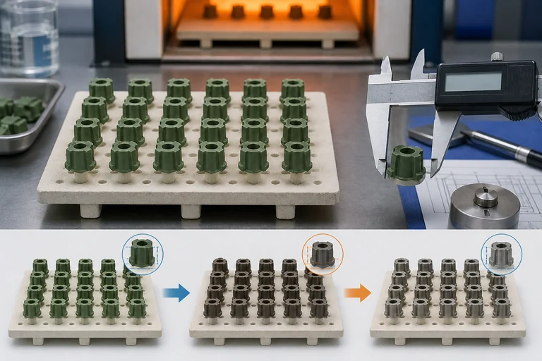
The process view shows how support, part state and dimensional inspection connect across the sintering route.
| Stage | What can change the result | Useful evidence |
|---|---|---|
| Feedstock and molding | Powder/binder consistency and green density | Lot identity, molding conditions and green dimensions |
| Debinding | Residual binder, cracking, distortion or contamination | Debinding route, inspection and mass/change checks as applicable |
| Loading and support | Gravity, contact, gas access and local thermal response | Fixture, orientation, stack map and load density |
| Sintering cycle | Heating, holds, atmosphere/vacuum and cooling | Recorded recipe and furnace condition |
| Inspection | Measurement method and part-state consistency | Defined datum scheme, sampling and trend chart |
Fixture and load design influence final geometry
Support must hold the green or debound part without causing a local mark, blocked shrinkage path or uneven heat transfer. A fixture selected only for loading convenience may not represent the geometry during densification. Use repeatable orientation and load density, especially for thin, long or asymmetric components.
For a broader defect sequence, see the MIM Debinding and Sintering Defects Guide. That page helps separate cracking, blistering, contamination and distortion signals from the dimensional-control issue addressed here.
Build a dimensional qualification loop
- Define critical dimensions, datums, tolerances and measurement method.
- Capture feedstock lot, molding condition and green-part inspection results.
- Document the debinding state and loading fixture/orientation.
- Use the approved furnace recipe and record the cycle condition.
- Measure sufficient representative parts by location and lot to see real process variation.
- Use trend data to decide whether a correction belongs upstream, in loading or in the furnace recipe.
Do not change the recipe in isolation if an upstream variable has shifted. A documented change-control plan protects the correlation between green dimensions, sintering response and final tolerances.
MIM furnace configuration should be reviewed with the binder system, material family, debinding route, load support, temperature curve, vacuum or gas requirement, cooling method and dimensional-qualification plan. Stable equipment conditions make it easier to identify true upstream variation. Start with Vacuum Furnace Systems to compare furnace families, then use the Vacuum Sintering Furnace system family when the MIM process window, loading method or production scale changes.
For a production route that integrates binder removal and sintering, review the Metal Injection Molding Vacuum Debinding and Sintering Furnace as the more specific configuration path after the category selection above.
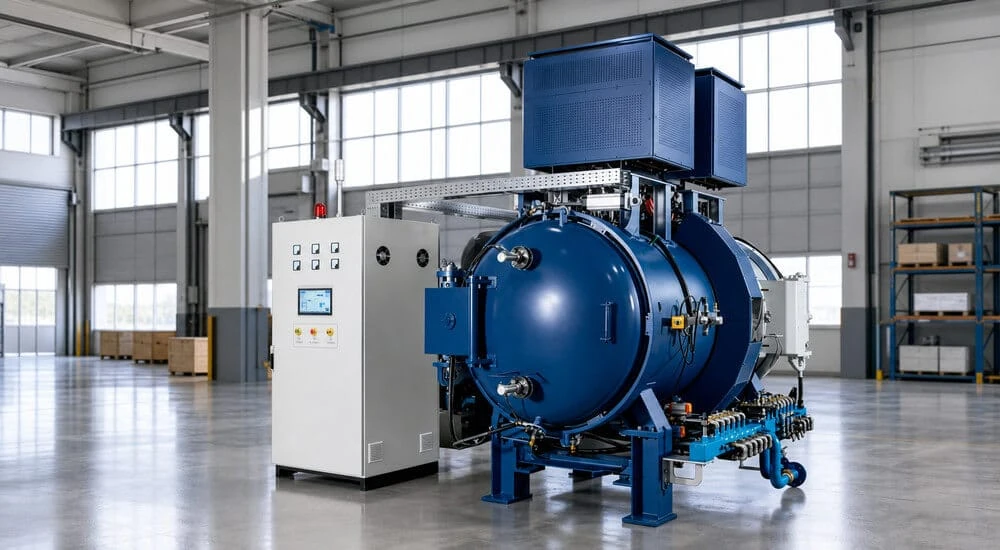
MIM Vacuum Debinding and Sintering Furnace
Process configuration should support the actual MIM material, binder removal, load geometry and repeatable thermal curve needed for qualified dimensions.
- Debinding and sintering process review
- Load and support configuration
- Data capture for dimensional qualification
What to include in your enquiry
Provide the material and dimensional-control information for a meaningful MIM review.
- Feedstock/material family, binder route and green-part drawing
- Critical finished dimensions, tolerances and inspection method
- Debinding condition, fixture, orientation and load mass
- Target sintering cycle, vacuum/atmosphere requirement and cooling route
- Production quantity, lot traceability and acceptance records
Technical references
- MPIF Standard 35-MIM — Materials Standards for Metal Injection Molded Parts — official Metal Powder Industries Federation reference for current MIM material-property data used in component material specification.