
Slow Pump-Down in a Vacuum Furnace: A Diagnostic Sequence
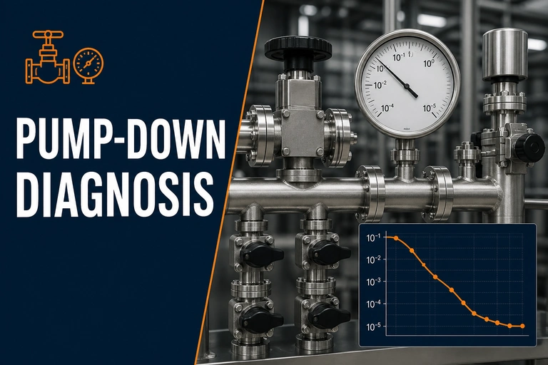
Slow pump down vacuum furnace diagnosis should separate a real leak from moisture, outgassing, restrictions and pump-system limits before a repair is chosen. Compare one controlled baseline condition with the affected cycle to make the next check meaningful.
Slow Pump Down Vacuum Furnace: First Checks
Slow pump-down is a comparison problem. Start with a known-good cycle time and a repeatable furnace condition, then separate gas load, conductance, pumping performance, valve position and measurement. Replacing a pump before that separation can conceal the actual cause and add cost without restoring cycle time.
What slow pump-down actually means
“Slow” only has meaning against a defined chamber condition: the same furnace, starting atmosphere, clean or loaded state, material, fixture mass, temperature and endpoint. A long evacuation after a wet load, fresh insulation repair or binder-containing process can be expected. The same delay on a clean, empty, cool chamber merits a different investigation.
Record the pressure-versus-time curve instead of relying on a single final number. The point at which the curve departs from normal helps indicate whether the issue is early-stage bulk gas removal, a restriction in the line, reduced pump performance, a control sequence issue or gas release at lower pressure.
Five diagnostic branches to check
This map shows why a slow pump-down investigation should follow chamber, load, valve and pump-line branches rather than changing equipment at random.
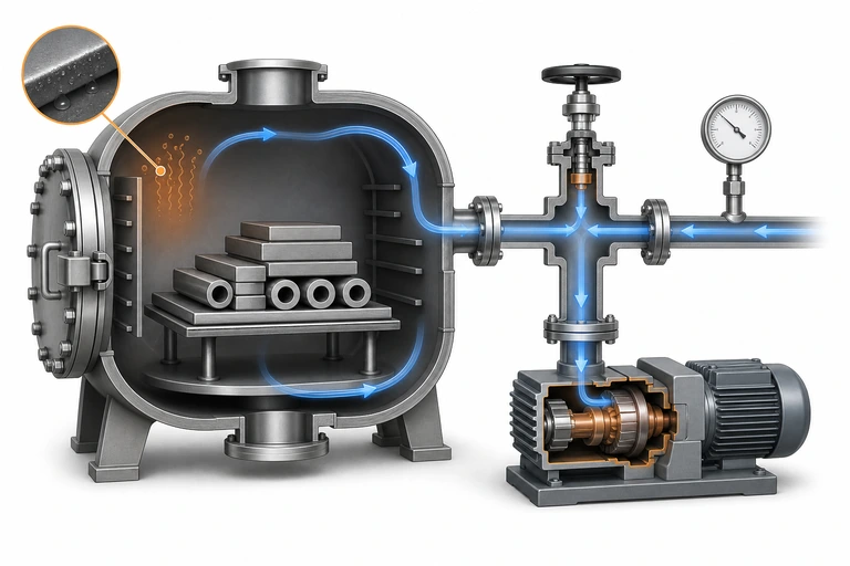
| Branch | Typical clue | Useful controlled check |
|---|---|---|
| Load and chamber gas release | Delay occurs after wet, oily, porous or binder-containing loads | Compare the approved empty condition with a representative load |
| Conductance or restriction | Pressure response differs across gauges or after recent piping work | Verify valves, line routing, filters and isolation positions |
| Pumping train | Empty-chamber curve changes with the same configuration | Review pump condition, backing performance and service history |
| Leakage or valve bypass | Evacuation stalls or recovery is inconsistent | Use a controlled isolation and leak-rate test |
| Measurement and controls | Displayed pressure conflicts with process behaviour | Cross-check gauges, ranges, interlocks and logged events |
Start with load condition before changing equipment
Water, cleaning residue, cutting fluid, polymer binder, trapped blind holes and porous fixtures can create a large gas load. A vacuum system is then doing the work it was asked to do; the corrective action may be cleaning, pre-drying, venting paths, fixture design or a different preheat and hold sequence. Treating that case as a pump failure can create a recurring production problem.
Make a short comparison log: load description, material condition, fixture arrangement, maximum load mass, starting temperature, time to each pressure milestone, and any process-gas or valve events. This gives maintenance and process teams a common record.
Isolate the system logically
- Verify the pressure reading with the correct gauge range and a recorded starting state.
- Run the approved empty-chamber comparison, if it is safe for the furnace and process.
- Check that all required valves open, close and isolate in the intended sequence.
- Inspect obvious restrictions: service valves, filters, traps, lines and maintenance changes.
- Compare pump performance only after the chamber and line branches have been separated.
- Confirm any repair with the original pump-down trace and a suitable leak-rate check.
If the final base pressure is also elevated, use the separate High Base Pressure Troubleshooting guide. For planned checks that reduce avoidable recovery time, review the Preventive Maintenance Checklist.
Vacuum-system design should match the chamber volume, hot-zone materials, load gas release, target pressure, process gases and production cadence. A quote based only on an ultimate vacuum value does not establish pump-down performance for a real production load.
For first-pass equipment selection, use Vacuum Furnace Systems to compare architectures and the Vacuum Heat Treatment Furnace system family to frame the process requirements. When slow pump-down affects a gas-quench process, review the Vacuum Gas Quenching Furnace to discuss chamber/load conditions, gas cooling and recovery timing in one equipment brief.
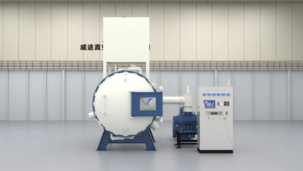
Vacuum Heat Treatment Furnace
A configured system should be reviewed against the actual load, target cycle and data requirements so pumping, heating and cooling work as one process system.
- Vacuum train matched to the process
- Logged process events and alarms
- Configurable loading and cooling arrangement
What to include in your enquiry
A useful review starts with the trace, load and current process requirement.
- Furnace model, chamber dimensions and pump configuration
- Normal and current pump-down times at defined pressure points
- Load material, mass, binder or contamination sources and fixture layout
- Target vacuum, process gas, temperature and cycle-time requirement
- Recent maintenance, pump service or control changes
Technical references
- ISO 21360-1 — Vacuum-Pump Performance — official ISO reference for measuring pump performance, including the pump-down method and influences such as leaks and desorption.
- ASTM E432 — Guide for Selection of a Leak Testing Method — official ASTM reference for selecting a leak-testing approach when a pump-down trend needs to be separated from leakage effects.