
Vacuum Brazing Stainless Steel: Material, Filler and Cycle-Design Guide
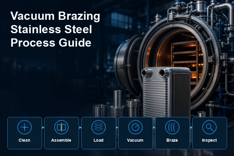
Stainless steel is frequently vacuum brazed for heat exchangers, sensor housings, aerospace hardware, medical components and fluid assemblies because the process can produce clean joints without flux residue. But “stainless steel” is not a single material condition, and a reliable process cannot be selected from a temperature alone.
| Decision | Input required | Why it matters | Evidence |
|---|---|---|---|
| Base metal condition | Grade, heat treatment, coating and surface history | Oxides and prior processing affect wetting and properties | Material certificate and preparation record |
| Filler selection | Service temperature, corrosion, strength and gap | Composition influences flow and joint performance | Approved filler specification |
| Thermal profile | Mass distribution, filler range and metallurgical limits | Heating balance and hold time affect flow and distortion | Recorded cycle and load temperatures |
| Inspection | Leak, strength, appearance or dimensional requirement | The acceptance method must match the product risk | Inspection plan and qualified result |
Vacuum brazing stainless steel starts with the base material
Identify the stainless grade, heat-treatment condition, final service temperature, corrosion requirement, permitted distortion and joint-strength/leak requirement. Austenitic, ferritic, martensitic and stabilized grades can behave differently during high-temperature brazing. A cycle that produces an acceptable joint may still change base-metal properties or corrosion behavior if it is not evaluated for the material and service condition.
The part drawing should state what the joint must do: carry load, seal pressure, conduct heat, remain corrosion resistant, or meet a specific inspection standard. This determines the filler, joint geometry and acceptance plan.
Select filler with the whole system in mind
High-temperature nickel-base filler metals are commonly used for vacuum brazing of stainless steels, but the correct family depends on the materials, service temperature, joint gap, flow behavior and allowable diffusion effects. The filler supplier should provide its melting range, recommended process window, gap guidance and compatibility information.
Avoid choosing a filler only because it has a lower brazing temperature. A lower temperature may help control distortion, yet may compromise service performance or introduce a different compatibility risk. Use representative qualification coupons before releasing a production recipe.
Prepare surfaces and control the joint
Degrease and clean parts with an approved method, then control handling and storage. Surface oxides, residues, fingerprints and unapproved marking materials can prevent wetting or raise the contamination load in the chamber. Keep the joint clearance and filler placement consistent; vacuum does not compensate for a gap that varies outside the proven process window.
Use fixtures that maintain location but do not lock the assembly against normal thermal expansion. For complex structures, provide paths that let trapped gas escape during evacuation and do not place fixture mass where it will shadow a critical joint.
Build a temperature profile around evidence
An effective profile normally includes controlled heat-up, appropriate equalization where geometry requires it, a brazing hold supported by the filler and joint qualification, and controlled cooling after the filler has solidified. The exact rates and hold times are part-specific. Faster is not automatically better: it may create temperature gradients, disturb filler placement or increase distortion.
Monitor the vacuum trend as well as temperature. A pressure rise during heat can signal residual moisture, binder, oil or trapped gas. Resolve contamination problems through preparation and equipment control rather than merely extending the high-temperature hold.
Inspect what matters to the application
Use the inspection plan agreed for the part: visual examination, dimensional check, leak test, metallographic sectioning, radiography, pressure test or mechanical testing as applicable. Build feedback from inspection into the next lot. A repeated defect pattern is valuable evidence about the relationship among joint design, preparation, fixture and cycle.
For an equipment discussion, send SYNHTE the stainless grade, component drawing, filler proposal, load size, required leak/strength criteria, temperature range, target throughput and any customer qualification standard. That is enough to begin matching a high-temperature vacuum brazing furnace to the real process.
Equipment ownership is not the only development route. Manufacturers comparing a dedicated vacuum brazing furnace can first use vacuum brazing services for sample trials, joint validation or early production. Trial evidence should still record the furnace condition, fixture, filler placement and load profile so that it can support a later equipment specification.
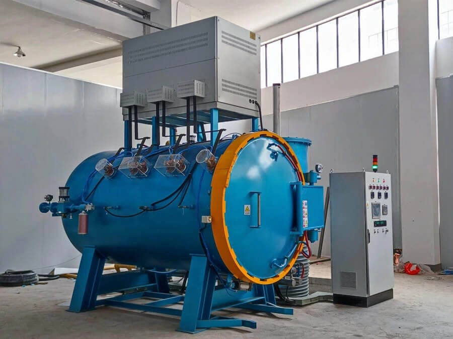
High-Temperature Vacuum Brazing Furnace
Stainless assemblies often combine thin sections, complex flow paths and strict cleanliness requirements. The selected furnace should support the work-zone size, uniform heating, vacuum level, data recording and cooling approach required by the qualified assembly.
- Controlled stainless-steel brazing cycles
- Work-zone and load matching
- Vacuum and cooling data records
What to include in your enquiry
These details let the engineering team respond with a relevant configuration instead of a generic catalogue answer:
- Stainless-steel grade and material condition
- Filler alloy or approved filler family
- Assembly drawing, joint gap and maximum load size
- Service temperature, corrosion and strength requirements
- Inspection method and production volume
Build a stainless-steel brazing process around your acceptance criteria
Provide the stainless grade, drawing, filler proposal, leak or strength criteria, load size and production target. Send the project details to SYNHTE for a brazing-furnace configuration review.