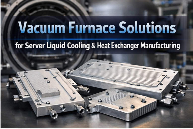
Cold plates & liquid-cooling modules
For EV batteries, power electronics, data-center cooling and other assemblies where internal cleanliness and leak integrity are purchasing criteria.
Batch Vacuum Aluminum Brazing
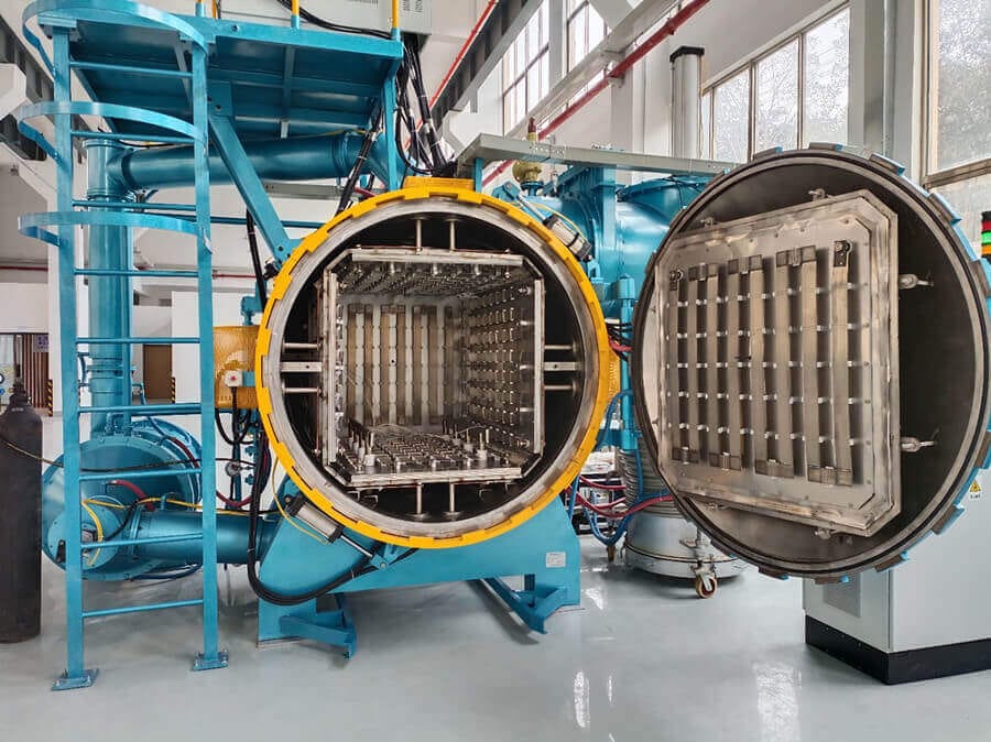
Configure a flux-free batch furnace around the aluminum assembly—not a generic chamber size. SYNHTE aligns the work zone, load mass, thermal uniformity, vacuum performance, fixturing, cooling and acceptance plan for heat exchangers, cold plates and precision cooling assemblies.

Application fit
Vacuum aluminum brazing depends on the material/filler system, surface condition, joint design, load arrangement, thermal profile and vacuum condition working together. The equipment brief should begin with the real assembly and its acceptance requirements.
For EV batteries, power electronics, data-center cooling and other assemblies where internal cleanliness and leak integrity are purchasing criteria.
Configure the work zone and heating layout around core dimensions, fixture mass, load density and the qualified braze cycle.
Support mixed geometries and batch changeovers where production flexibility matters more than a dedicated continuous line.
Use controlled loading and multi-zone heating where joint fill, distortion, appearance and dimensional stability must be verified.
Physical evidence
A usable work zone is more than nominal chamber dimensions. Include the tray, fixture, thermocouples, clearance for circulation and the heaviest credible production load.


Route selection
This page owns the batch high-vacuum aluminum intent. Continuous output and high-temperature non-aluminum brazing are separate equipment decisions.
Best fit when the assembly is aluminum, a flux-free route is required, batches or geometries change, and the furnace must be configured around a qualified load.
Use a continuous-line assessment when a stable part family, takt time, transfer method, loading automation and sustained throughput define the project.
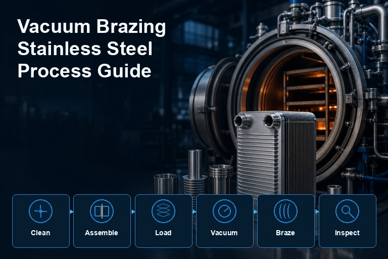
Use the high-temperature route for stainless steel, superalloy, carbide or other non-aluminum joining systems that require a different hot-zone architecture.
Engineering inputs
Do not lock a model from temperature and chamber size alone. The first technical review should connect the material system, preparation route, joint design and production requirement.
Name every aluminum grade, clad layer, filler form and any magnesium-bearing component or getter strategy. Compatibility must be qualified for the actual assembly.
Define degreasing, rinsing/drying, protected handling, storage limit and any qualified oxide-management step. Vacuum cannot rescue contaminated parts.
Provide joint sections, tolerances at temperature, filler placement, blind passages, orientation and acceptable runout rather than a single generic gap.
Include the complete loaded tray, quantity, position, fixture contacts, thermocouple access and worst-case production mass.
State annual volume, shifts, batches per day, target cycle time and product mix so chamber count, loading and cooling are evaluated honestly.
Define leak/pressure testing, appearance, dimensions, strength or metallography, data records, traceability and the representative qualification load.
Furnace architecture
The final design is project-specific, but the architecture should make its process functions and acceptance points visible before purchase.
Nickel-chromium heating elements and an all-metal insulation approach support the aluminum temperature range. Zone count and sensor layout are matched to the work zone and load.
Backing, booster/high-vacuum stages, gauges, valves and pipe conductance are selected to reach and hold the required condition for the configured chamber and process.
A controlled getter/material strategy and a maintainable magnesium trap help protect the vacuum train. The joint/filler system and cleaning route remain part of qualification.
Cooling capacity, direction and recipe controls should fit part geometry, fixture mass, distortion risk and the required unload temperature.
Single- or double-door layouts, loading carts and trays are configured around the plant route, chamber length and required separation of load/unload activity.
Automatic/manual modes, interlocks, alarms, temperature/vacuum records and user access support repeatable production and an auditable qualification package.
Qualified workflow
Exact setpoints and hold times remain part-, filler- and load-specific. The furnace must reproduce the approved recipe and record the evidence used for release.
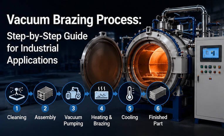
Verify materials, filler, joint drawing, surface route and permitted storage/handling condition.
Control orientation, filler placement, vents, support points, thermal expansion and load identity.
Position the tray and agreed thermocouples without creating thermal shadows or blocking evacuation.
Run the qualified pumpdown, ramp, equalization and brazing sequence while recording temperature and vacuum.
Use the agreed vacuum or inert-gas cooling strategy within distortion, safety and unload-temperature limits.
Apply the named leak, pressure, visual, dimensional or destructive checks with traceable cycle data.
VTB catalog range
The following values are catalog reference points—not a substitute for the technical agreement. Power, load capacity, chamber layout, zone count and utilities can change with the final project configuration.
| Model | Usable work zone (W×H×L) | Catalog load | Heating power | Max. temp. | Uniformity | Ultimate vacuum | Pressure rise |
|---|---|---|---|---|---|---|---|
| VTB-335 | 300×300×500 mm | 100 kg | 40 kW | 750°C | ±3°C | 6×10⁻⁴ Pa | 0.3 Pa/h |
| VTB-446 | 400×400×600 mm | 200 kg | 60 kW | 750°C | ±3°C | 6×10⁻⁴ Pa | 0.3 Pa/h |
| VTB-557 | 500×500×700 mm | 300 kg | 80 kW | 750°C | ±3°C | 6×10⁻⁴ Pa | 0.3 Pa/h |
| VTB-669 | 600×600×900 mm | 500 kg | 100 kW | 750°C | ±3°C | 6×10⁻⁴ Pa | 0.3 Pa/h |
| VTB-8812 | 800×800×1200 mm | 800 kg | 160 kW | 750°C | ±3°C | 6×10⁻⁴ Pa | 0.3 Pa/h |
| VTB-9912 | 900×900×1200 mm | 1000 kg | 180 kW | 750°C | ±3°C | 6×10⁻⁴ Pa | 0.3 Pa/h |
| VTB-9920 | 900×900×2000 mm | 1500 kg | 400 kW | 750°C | ±3°C | 6×10⁻⁴ Pa | 0.3 Pa/h |
| VTB-3.6L | 1100×1100×3600 mm | 2000 kg | 500 kW | 750°C | ±3°C | 6×10⁻⁴ Pa | 0.3 Pa/h |
On a narrow screen, swipe horizontally to compare every column.
Configuration boundary: project-specific VTB-9920 documentation, for example, can carry a different installed power or agreed load than the catalog row. The signed technical agreement and FAT protocol govern the delivered system.
FAT, SAT & process release
Acceptance wording should name the furnace state, load, measurement method, instruments, hold time and pass/fail limit. A catalog number without a test condition is incomplete.
Ultimate vacuum, working-vacuum observation, pumpdown and pressure-rise testing with the agreed cold/empty/clean condition and calibrated gauges.
Temperature uniformity survey at agreed setpoints, sensor locations and stabilization conditions; loaded trial profiling where required.
Recipes, manual/automatic operation, alarms, over-temperature, cooling-water and vacuum interlocks, data recording and user access.
Usable envelope, door and loading operation, tray/fixture fit, plant power, cooling water, gas, exhaust, maintenance clearance and documentation.
Part, coupon or representative load; thermocouple plan; agreed recipe; appearance and dimensional review; change-control record.
Leak/pressure method, limit and test medium plus any visual, strength, metallographic, cleanliness or traceability requirement agreed for release.
Technical RFQ package
A useful quotation starts with enough information to select the work zone, pumping, heating zones, loading, cooling and acceptance route.
Frequently asked questions
The final answer depends on the material, filler, geometry, load and acceptance plan. These answers define the decision boundary without replacing qualification.
This page covers a batch high-vacuum aluminum brazing furnace. It suits mixed geometries, development work and repeat production in discrete loads. A stable part family with a defined takt time and automated transfer may justify a continuous-line review.
No. The approved cycle depends on the base alloy, filler/clad system, joint design, surface condition, fixture, load mass and required result. The 750°C value is a furnace maximum, not a universal brazing setpoint.
Uniformity depends on setpoint, stabilized state, measurement locations, instrument accuracy and whether the furnace is empty or loaded. Put those conditions into the FAT protocol so the value is repeatable and enforceable.
In a qualified VAB system, magnesium can be present in the alloy/filler system or used through an agreed getter strategy. Its evaporation helps bind residual oxygen and water vapor and supports oxide disruption. Material selection, quantity, trapping and furnace maintenance must be controlled together.
Define the evidence before the trial: leak or pressure test method and limit, visual criteria, dimensions, strength or metallography where required, and the cycle data tied to the load. A leak test alone does not qualify every part of the process.
Related engineering guides
These links keep the commercial product page as the equipment owner while deeper informational questions remain on dedicated knowledge pages.
Download the current reference document or compare all available SYNHTE technical resources.