
Vacuum Oil Quenching vs Gas Quenching: How to Select the Process
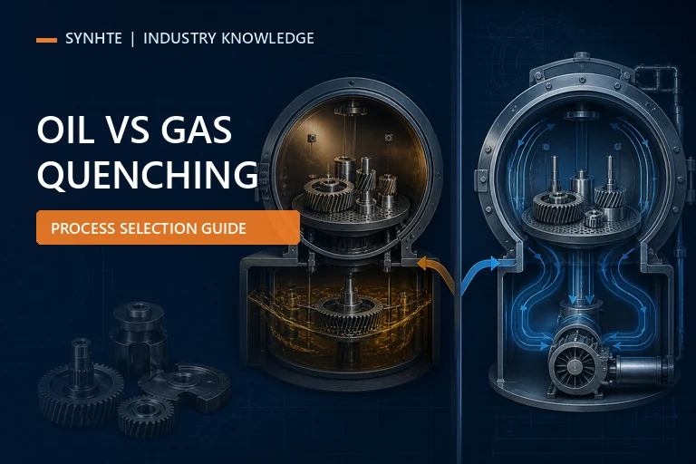
Vacuum oil quenching is generally the stronger candidate when the specified steel and section require more severe cooling, while high-pressure gas quenching is generally the stronger candidate when it can achieve the required metallurgical response with lower contamination and simpler post-quench handling. The final selection must be confirmed with production-representative loads, part-level hardness or microstructure evidence, distortion and crack checks, and the controlling customer or material specification.
Start with the required result, not a quenchant preference
Define the decision in measurable terms: steel grade and starting condition; minimum core or through hardness; critical section thickness; allowed microstructure when specified; dimensions that are sensitive to movement; crack-detection requirement; surface cleanliness; batch mass; fixture arrangement; and throughput. Then identify the slowest-cooling and most distortion-sensitive locations in the actual part. This prevents teams from selecting gas only because it is clean or oil only because it is generally more severe.
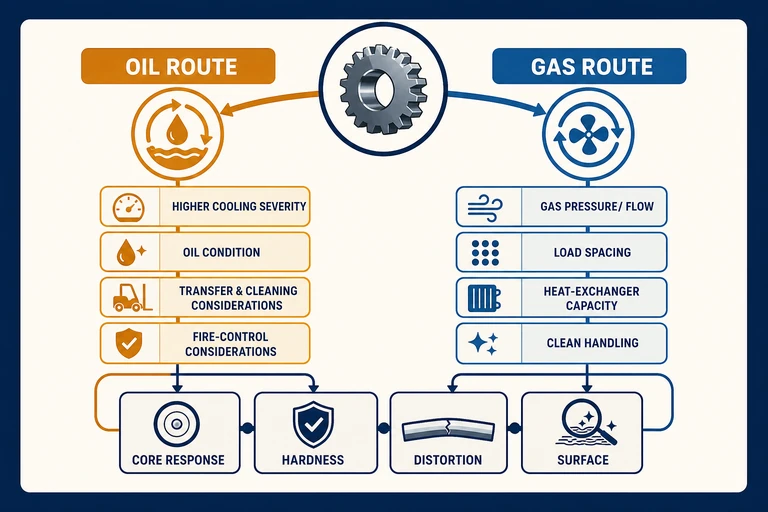
Oil and gas quenching require different process controls, but both routes must be verified against the same part-level acceptance criteria.
Read hardenability and section response before comparing equipment
Hardenability describes how deeply a steel can transform under a given cooling condition; it is not the same as maximum surface hardness. Alloy chemistry, austenitizing condition, prior microstructure, grain size, section thickness, and the real cooling path interact. A highly hardenable steel in a modest section may reach the required response with high-pressure gas cooling, while a lower-hardenability steel or a heavier section may need a more severe route. The approved material procedure and representative test evidence must decide that boundary.
Geometry can be as important as nominal thickness. A gear has teeth, rim, web, and hub regions with different masses and heat-flow paths. Sharp transitions, blind holes, thin walls beside heavy bosses, and asymmetric features can create local stress during transformation and cooling. Faster cooling may help the metallurgical response but increase movement or cracking risk in a vulnerable feature. Slower cooling may reduce thermal gradients but fail the required core response. The engineering task is to find an acceptable window, not to maximize cooling rate.
Use material data to form a hypothesis, then verify it with representative loads. Cooling simulations, transformation diagrams, or prior qualified recipes can guide test design, but they do not prove the result in a different furnace, fixture, batch mass, or part geometry. Customer and controlling specifications take precedence when they define the quenchant, minimum cooling behavior, or test method.
Compare the process controls that can change the cooling result
Oil quenching commonly places the heated load into a separate oil chamber. The result depends on transfer time, oil identity and condition, oil temperature, circulation or agitation, load entry, vapor removal, contamination control, and the relationship between part geometry and fluid movement. A nominal oil tank is not evidence of uniform quenching. The system must keep the qualified oil condition and movement repeatable, and the operating plan must address cleaning, carryover, fire protection, and oil maintenance.
Gas quenching keeps the load in a closed circuit and uses the selected gas, pressure, fan performance, heat exchanger, flow direction, and fixture spacing to remove heat. Cooling capability is therefore a system property. Dense nesting, broad fixture plates, shielded cavities, or a heavy central part can reduce local flow even when the pressure setpoint is correct. Fixture spacing and unobstructed airflow paths belong in the qualified load definition; see Vacuum Gas Quenching Load Design.
| Decision area | Oil-quench control | Gas-quench control |
|---|---|---|
| Cooling delivery | Transfer, immersion, circulation and oil condition | Gas identity, pressure, fan, flow path and heat exchanger |
| Load sensitivity | Entry orientation, vapor behavior and fluid access | Spacing, shielding, fixture blockage and flow reversal |
| Surface and handling | Oil carryover, cleaning and contamination controls | Closed clean route and dry-gas management |
| Facility controls | Oil management and fire-control provisions | Gas supply, pressure system and cooling utilities |
Qualify the selected route with production-representative evidence
Qualification should connect the complete load history to part results. Record the furnace, recipe revision, material lot, starting condition, load drawing, fixture identity, batch mass, sensor arrangement, heating record, transfer or quench initiation, route-specific cooling variables, alarms, and maintenance status. Preserve part positions so the center, edge, top, bottom, exposed, and shielded locations can be compared rather than pooled into one reassuring average.
Acceptance may include hardness by specified location, microstructure or case response when required, dimensions before and after treatment, crack inspection, surface condition, and mechanical tests defined by the product specification. The sampling plan should reflect part risk, load size, governing quality system, and the cost of missing a weak region. Confirmation loads should include normal production variation instead of repeating one unusually light and carefully arranged demonstration.
Compare not only average results but also spread and positional bias. A route that reaches hardness but repeatedly moves one critical feature may be less capable than a slightly different cooling arrangement. A clean gas-quenched surface does not compensate for an under-transformed core. An oil-quenched part with acceptable hardness still needs crack, distortion, and cleanliness evidence. Define change triggers for material grade, section, load density, fixture, oil batch, gas route, pressure, fan work, heat-exchanger service, or recipe revision so the qualification remains meaningful.
Translate material needs into oil- or gas-quenching equipment requirements
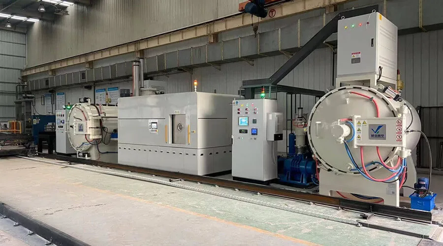
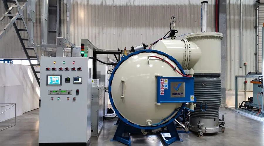
SYNHTE's Vacuum Heat Treatment Furnace range includes dedicated oil- and gas-quenching systems. For an oil route, review the Vacuum Oil Quenching Furnace as a double-chamber platform with separate heating and oil-quenching zones. For a gas route, the Vacuum Gas Quenching Furnace describes a high-pressure inert-gas cooling platform. Select the final configuration against the actual steel, section, load, acceptance criteria, utilities, and safety requirements.
Ask suppliers to discuss usable work-zone dimensions, approved load mass, hot-zone compatibility, heating uniformity, transfer or gas-flow behavior, fixture access, cooling-system capacity, data acquisition, recipe control, maintenance access, and facility interfaces. Request evidence that is relevant to the proposed load rather than extrapolating from an empty-chamber statement. A technically useful request for quotation includes the part drawing, material and procedure, representative load map, acceptance criteria, expected volume, and the reason the current route is inadequate.
Vacuum Oil or Gas Quenching System
Select the cooling route from the material, section, load, distortion limit, cleanliness target and qualification evidence. SYNHTE offers dedicated vacuum oil-quenching and high-pressure gas-quenching systems.
What to include in your enquiry
- Material or abrasive system, starting condition and controlling specification
- Part, joint, fixture and representative production-load drawings
- Current process route, fixed variables and development questions
- Required properties, dimensions, inspection methods and acceptance limits
- Typical batch volume, throughput target, utilities and site constraints