
Vacuum Brazing Fixture Materials: Metals, Graphite and C/C
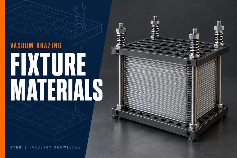
Choose vacuum brazing fixture materials by the job each component must perform throughout the loaded cycle. A platen must support the assembly, a locating feature must control position, and a spring must retain useful force while allowing movement. Stainless steels, nickel alloys, graphite and carbon/carbon composites are candidates for different duties—not interchangeable grades on a single “best material” list.
For aluminum plate-fin heat exchangers, the practical objective is to preserve the required joint contact and finished geometry without contamination or excessive constraint. Start with the workpiece, filler system, thermal cycle and acceptance criteria. Then qualify a material, geometry and surface condition together.
Select vacuum brazing fixture materials by function
In a plate-fin heat-exchanger assembly, the core sits between upper and lower platens. Tie rods transmit the reaction around the stack, while springs provide compliance where the qualified design requires it. This separates the locating surfaces from the parts that carry clamping force; they do not automatically need the same material.
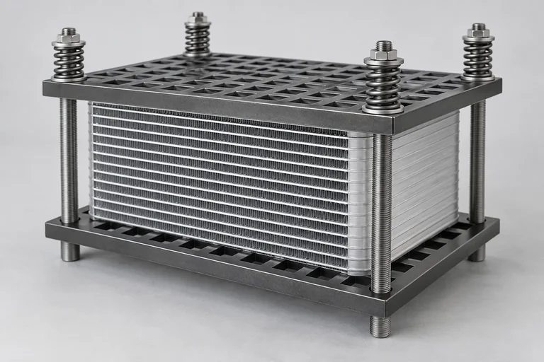
Draw that load path before selecting a grade. Identify which surfaces establish the datum, which support the thin assembly, and which transmit force. A platen that appears rigid on a bench can still introduce uneven pressure when its supports, openings or contact pads change. More clamping force is not automatically better: it must remain compatible with the core and joint design.
Record the assembled dimensions, unsupported spans, lifting points and expected movement. Separate replaceable contact pads from reusable structural parts where that arrangement is practical. This makes later material trials easier to interpret because a change in contact material need not also change the whole fixture geometry.
Choose metal grades for time at temperature
A room-temperature tensile value does not establish whether a loaded platen or rod will retain its geometry through repeated brazing cycles. Outokumpu identifies creep strength as an important design consideration for high-temperature stainless steels. Its high-temperature grade guidance also distinguishes alloy families rather than treating all stainless steels as equivalent.
For a proposed metal component, request the exact grade, product form, heat-treatment condition and relevant elevated-temperature data. Assess stress at holes, bends, welds and bearing surfaces, not only an average load divided by the gross section. An oxidation-resistance rating alone does not establish suitability for a particular vacuum brazing load or contact interface.
Springs need a separate review. Special Metals' INCONEL alloy X-750 bulletin presents relaxation behavior for specified material conditions, temperatures, stresses and times. Consequently, a nickel-alloy name is not a complete spring specification. Define installed compression, working travel and acceptable force loss; obtain evidence for that condition. A spring that returns to a plausible free height after cooling has not, by that observation alone, demonstrated the required hot clamping force.
Distinguish graphite, C/C and polymer composites
“Carbon fiber” does not identify a finished fixture material. Carbon/carbon, abbreviated C/C, combines carbon reinforcement with a carbon or graphite matrix. It is not the same material as carbon-fiber-reinforced polymer, commonly abbreviated CFRP. SGL Carbon's SIGRABOND material overview describes C/C and its different grades for furnace components and charging systems. A polymer-composite sheet must not be substituted merely because its reinforcement looks similar.
Graphite and C/C also require different component designs. Specify the actual grade, material orientation where relevant, machining details and attachment arrangement. Do not assume that a metal drawing can be reproduced unchanged in a carbon material. Ask the supplier to review local bearing loads and fastening details, and include handling damage in the inspection plan.
| Material family | Selection question | Evidence to request |
|---|---|---|
| Stainless or heat-resistant steel | Will the loaded frame or platen maintain acceptable geometry? | Exact grade, fabrication condition, hot-load assessment and dimensional results. |
| Nickel alloy | Does the selected condition meet the rod, fastener or spring duty? | Component-specific creep or relaxation data and a defined operating envelope. |
| Graphite | Are contact compatibility and the machined load-bearing details acceptable? | Grade and purity information, interface trials and damage criteria. |
| Carbon/carbon composite | Does the reinforcement architecture suit the actual load direction? | Grade, orientation, joint design and representative component testing. |
This is a screening checklist, not a ranking. The qualified assembly may use more than one family, with each interface evaluated as part of the complete load.
Allow for differential expansion and clamp load
Low fixture expansion is not automatically a guarantee of stable joint clearance. The relevant issue is relative movement between the workpiece, supports and force-transmitting components. Evaluate the directions that matter to the assembly rather than applying one expansion value to the entire fixture.
Consider a workpiece located against one datum and supported by a fixture rail. If their thermal growth differs, clearance at the opposite end changes during heating. A free end or designed sliding interface can accommodate that relative motion; locking both ends can convert it into unwanted constraint.

The same reasoning applies to a compressed stack: changes in stack height and tie-rod length alter the spring's working position. Check that the proposed travel remains within its qualified range throughout heating and cooling. Include contact-pad thickness and assembly tolerances. Cold clearance measurements are useful starting records, but the acceptance decision must also consider the heated configuration and the final part geometry.
Qualify contact surfaces and vacuum cleanliness
Approve the interface, not just the bulk material. Identify every surface that touches the part or sits where escaped filler could reach it. Review compatibility with the workpiece alloy, filler and cleaning route. Graphite should not be described as universally compatible with all brazing materials; a proposed coating or separator also needs process-specific evidence.
Use representative contact coupons or trial assemblies to check sticking, deposits, marking and effects on the joint. Keep machining fluids, handling residues, loose particles and unapproved lubricants out of the loading process. Define cleaning, drying and storage instructions for the finished fixture, including porous components where applicable. A clean incoming material certificate cannot substitute for control of a fixture that has already been machined, handled and repeatedly exposed to production loads.
Prove a lightweight redesign in the loaded cycle
Reducing fixture mass may change how the load heats and cools, but it does not establish a shorter qualified cycle or a lower cost per acceptable part. A thinner platen, different material or replacement strapping arrangement also changes support, force transmission and handling. Treat it as a controlled fixture revision.
Compare the existing and proposed designs using representative parts, loading positions and acceptance tests. Record workpiece temperature behavior where the qualification requires it, finished dimensions, leak or joint-quality results, fixture distortion and spring condition. Establish inspection intervals and retirement criteria before repeated production use.
Evaluate economics from accepted output: include loading time, cleaning, replacement components, repair effort and rejected parts. Keep the original configuration traceable during the trial. Identify individual fixtures and replacement springs in the production record so that inspection trends can be linked to an actual configuration. Mixed, unrecorded component batches make that comparison less reliable. If several variables change together, satisfactory results may support that complete configuration, but they will not identify which individual change produced the improvement.
Specify the fixture with the brazing furnace
Review the complete loaded envelope when comparing vacuum brazing furnace systems. Include the fixture, supports and handling clearances, not only the bare workpiece dimensions. Discuss load arrangement, heating exposure, temperature measurement and the approved cooling route alongside material selection.
For an aluminum brazing application, the High Vacuum Aluminum Brazing Furnace is a relevant equipment starting point. The proposed fixture still needs its own technical review; a furnace's application category does not qualify a particular spring, graphite contact or clamping method. Agree what evidence is needed from the loaded trial before freezing either the fixture drawing or production procedure.
Discuss the complete brazing load
Bring the workpiece and fixture requirements into the same equipment discussion. SYNHTE can review the application inputs for an aluminum vacuum brazing furnace, including the loaded dimensions, process route and intended acceptance checks.
What to include in a fixture review
- Workpiece alloy, filler system, part drawing and critical joint or flatness requirements.
- Fixture drawing, material grades, contact surfaces, spring details and complete loaded dimensions.
- Heating and cooling cycle, vacuum requirements, production loading pattern and handling method.
- Current inspection results, observed distortion or force-loss symptoms, and planned acceptance tests.
Send your application requirements to SYNHTE to frame the equipment and load review around the actual production task.
Technical references
- Outokumpu: High-temperature stainless steel grades — alloy-family distinctions and elevated-temperature design considerations.
- Special Metals: INCONEL alloy X-750 technical bulletin — condition-dependent spring and relaxation data.
- SGL Carbon: SIGRABOND carbon fiber-reinforced carbon — C/C material definition and grade-specific applications.