
Cold Plate Vacuum Brazing Quality: Leak Tightness, Strength and Flatness
Cold plate vacuum brazing quality depends on more than a leak-free perimeter. The process must join the specified internal interfaces, preserve open coolant passages and retain the required mounting-face geometry. Improve it by controlling the alloy and filler system, hot joint clearance, surface condition, fixture restraint and actual loaded thermal cycle, then verify sealing, structural performance, flow and flatness as separate outcomes.
Define quality at the external seal and internal bonds
A cold plate contains two different joining duties: the perimeter closes the pressure boundary, while internal lands or fins may also need to bond to the cover. Those internal bonds can support the cover and preserve the intended coolant route. An external leak test alone does not show whether they formed.
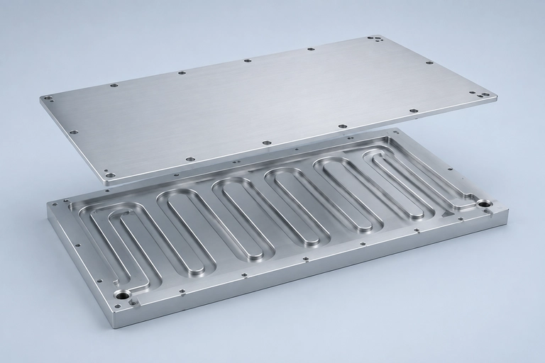
Begin with a joint map on the drawing. Identify pressure-boundary joints, cover-to-land interfaces, fin contacts, port connections and deliberately unjoined areas. For each interface, state its function and how its condition will be checked. A missing bond between neighboring passages may create an internal bypass without releasing coolant outside the plate. A local cover separation may also change pressure response even though the external seam appears sound.
Use this map to compare manufacturing routes fairly. Vacuum brazing can join accessible filler-bearing internal interfaces during the same furnace cycle as the perimeter. A perimeter-only joining operation does not automatically create those internal bonds. That distinction concerns the chosen joint layout, not a universal ranking of brazing versus friction stir welding. The preferred route must satisfy the actual geometry, pressure duty, thermal requirements and production economics.
Keep the initial quality baseline measurable: record the defect location, the process stage at which it was found, the applicable drawing limit and the test method. Separate external leaks, internal discontinuities, channel restriction and face distortion in the defect log. Combining all of them into one rejection percentage conceals different causes and makes later improvements difficult to attribute.
Match the base alloy, filler and hot joint clearance
Specify the complete material system before choosing a temperature program. Include the base-alloy designation and temper, cover and fin stock, any clad layer, filler designation and form, and the composition of ports or inserts entering the furnace. A process suitable for one aluminum assembly should not be transferred to a copper cold plate or a different alloy combination by changing only the setpoint.
The basic brazing window lies above the filler liquidus while remaining compatible with the parent material. The available margin must accommodate real part-to-part temperature differences, local overheating and the time needed to fill the joints. Base-metal erosion and loss of the incoming heat-treated condition also require review. State the required final material condition; do not assume an incoming temper survives brazing or that a later heat treatment is automatically compatible with the assembled plate.
Filler amount and location are as important as nominal composition. A controlled clad layer or shaped preform can improve repeatability, but each requires its own acceptance controls. Check thickness or mass, coverage at internal lands, retention during handling and the available escape path for excess filler. Too much filler can narrow a passage; too little can leave an incomplete interface. A large visible external fillet is not evidence that the internal joints received the right amount.
Specify clearance for the relevant process state. Room-temperature measurements must be interpreted with part tolerances, cover flatness, fixture restraint and differential expansion in mind. Use the qualified alloy-and-filler combination to establish acceptable hot clearance rather than copying one gap from another cold plate. Inspect the stack before brazing and correlate it with sectioned trial parts. When a change to filler chemistry or a coating is proposed, treat it as a development variable requiring compatibility and contamination evidence.
Protect the cleaned surfaces through assembly
Surface preparation must remove machining residues and contamination while leaving the joint surfaces suitable for the qualified oxide-management route. Vacuum alone does not make an oily, wet or poorly prepared interface brazeable. Select cleaning chemistry and treatment limits for the actual alloy and clad condition, using the chemical supplier information and an approved plant procedure. Excessive attack of a thin clad layer can change the filler supply before assembly begins.
Design the cleaning load so that fluid reaches the surfaces and drains from passages. Avoid nested plates, trapped pockets and handling damage to thin fins or clad faces. Rinse quality, carryover between stages and verified drying matter alongside bath condition. A drying time that works for loose flat sheets may not dry a dense fin pack or an assembled blind passage. Confirm the condition of representative components instead of relying on oven air temperature alone.
After drying, use clean supports, suitable gloves and protected storage. Record the allowable exposure and the action required if parts exceed it. During assembly, prevent fixture coatings, adhesive residues, lint and fingerprints from reaching the intended joints. Inspect retained filler and vents before the stack disappears under the cover. This final pre-braze check is often the last practical opportunity to see a misplaced preform or trapped particle directly.
When wetness or contamination is suspected, quarantine the affected assembly and review the preparation record. Raising the peak temperature is not a cleaning correction and may increase erosion or distortion. Keep cleaning rework within an approved route, especially where repeated chemical treatment could thin the material or alter its surface condition.
Control fixture restraint and the loaded thermal cycle
A fixture must maintain the intended alignment and contact without crushing thin features or preventing necessary thermal movement. Review the support pattern, locator scheme, restraint force, expansion allowance and release condition. A broad plate may bow between supports; concentrated restraint can mark a mounting face; an overly rigid setup can alter the joint clearance as the assembly heats.
Reduce unnecessary fixture thermal mass only while preserving stiffness, temperature capability and chemical compatibility. Material selection is a system decision: expansion, outgassing, filler wetting and contamination risk all matter. Validate any stop-off coating for the intended atmosphere and keep it out of required joints. A lightweight material or additive-manufactured fixture is not inherently suitable for a vacuum brazing cycle.
For cold plate vacuum brazing, qualify the loaded temperature history, not just the controller trace. Place suitable load thermocouples at locations chosen to represent anticipated hot and cold regions, including areas influenced by fixture contacts, load density or cover thickness. Record attachment method and sensor positions so later trials can be compared. Empty-furnace temperature uniformity and controller accuracy answer different questions from the temperature spread inside a production load.
Use equalization stages where the measured response demonstrates a need, and choose the brazing hold from joint formation evidence and the allowable material exposure. Increasing temperature or extending the hold to repair a cold location may overheat an already hot region. First examine loading, fixture mass, sensor location and heating-zone behavior. Link pressure history and any abnormal outgassing to the same timeline; an ultimate-vacuum figure from a clean empty chamber is not the working pressure throughout brazing.
Define cooling as part of the qualified cycle. Filler solidification, differential contraction and restraint release all affect final geometry. The fastest available cooling rate is not automatically the best rate for a broad thin plate. Confirm the transition to gas cooling, the unload condition and any post-braze treatment for the actual assembly. Preserve load orientation, fixture revision and cycle revision as traceable production variables.
Verify leakage, internal continuity and flatness separately
Choose acceptance evidence from the failure that must be excluded. A cold plate can pass one check and fail another because the methods interrogate different features. Agree the test medium, pressure or flow condition, temperature, instrument sensitivity, fixture arrangement and pass/fail limit before comparing results. State whether each check is a development test, a qualification sample or a production release requirement.
| Check | What it establishes | Control and limitation |
|---|---|---|
| External leakage | A through-path across the pressure boundary under the stated test conditions. | Use the specified tracer or pressure method, calibrated equipment and controlled fixtures. A pass does not prove every internal land is bonded. |
| Internal bond continuity | Whether specified cover-to-land or fin-to-plate interfaces have joined. | Qualify sectioning or a suitable nondestructive method against representative reference features. Access and joint orientation limit detectability. |
| Pressure capability | Whether the assembly withstands the specified pressure and loading sequence. | Define proof, burst or cyclic testing separately, with approved test medium, restraints and safety provisions. A proof test is not a burst rating. |
| Flow and thermal performance | Whether coolant follows the intended path with acceptable restriction and heat transfer. | Compare pressure drop and flow under controlled fluid conditions; correlate with a thermal test when required. A sealed bypass can escape an external leak test. |
| Flatness and dimensions | Whether the mounting face, ports and overall geometry meet the drawing after processing. | Measure in the stated free or restrained condition and at the agreed process stage. Preserve the result before any corrective machining. |
For hidden interfaces, demonstrate that the chosen nondestructive method can detect the relevant discontinuity in this geometry. Radiography and ultrasonic inspection have different sensitivities to joint orientation, access and defect type. Neither should be described as a complete substitute for representative sectioning without correlation evidence. During development, choose sections through high-risk internal lands, transitions and thermally distinct load positions, not only the easiest external fillet.
Measure flatness in the drawing-defined condition. Clamping a distorted part against an inspection fixture can hide free-state distortion; measuring only after face machining can hide what the brazing cycle changed. Record the agreed stage and support condition consistently. If corrective machining is part of production, verify the remaining wall thickness and repeat the required pressure-boundary checks after operations that could expose a defect.
Close the improvement loop with controlled trials. Select the dominant failure mode, hold unrelated variables steady, document the changed variable and compare like-for-like loads using the same acceptance methods. Repeat promising results across representative positions and subsequent batches before adopting the change. Report the sample size, defect definition and test conditions with any yield claim; a successful development piece is not a demonstrated production capability.
Specify the furnace around the qualified cold-plate load
Use the part and fixture package to compare vacuum brazing furnace systems. For a flux-free aluminum batch route, the VTB high-vacuum aluminum brazing furnace is the relevant starting point. Its live configuration guidance connects the aluminum-specific metal hot zone and heating arrangement with pumping, magnesium management, external circulation cooling and traceable controls. Final equipment requirements still depend on the material system and representative load.
Define the complete loaded envelope: cold plates, spacers, supports, tray, fixture and thermocouple clearance. Door access and hot-zone geometry determine whether that load can be positioned repeatably without damaging components or creating avoidable thermal shadows. Include the heaviest and densest credible batch in the equipment brief, not only an empty tray or a single demonstration plate.

Write acceptance conditions beside each equipment requirement. Pumpdown, pressure rise, temperature uniformity and cooling response need defined instrument locations, furnace condition and test load. A pressure-rise rate must also be interpreted with the chamber volume and outgassing conditions; it is not interchangeable with a leak-rate specification. Ask for representative loaded trials where process performance is part of the purchase agreement.
For an existing furnace, establish the current baseline before purchasing upgrades. Review maintenance condition, vacuum trends, temperature records, magnesium deposits where applicable, fixture changes and the actual defect map. Better data acquisition or zone control is useful when it addresses a demonstrated limitation. The practical objective is a repeatable approved joining window and a traceable release decision, not the lowest pressure or tightest controller number in isolation.
VTB High-Vacuum Aluminum Brazing Furnace
For an aluminum cold-plate batch process, discuss the VTB work zone, heating zones, magnesium-management arrangement, loading access and cooling configuration together with the representative assembly and acceptance plan.
What to include in your enquiry
- Exact material, incoming condition and governing drawing or specification
- Part, interface, fixture, stack and production-load drawings
- Required process outcome, acceptance methods, limits and sample locations
- Current process route, fixed variables, development questions and known risks
- Batch volume, data-retention needs, utilities, site interfaces and delivery requirements