
Aluminum Vacuum Brazing Filler Metal Placement: Clad Sheet, Foil and Preforms
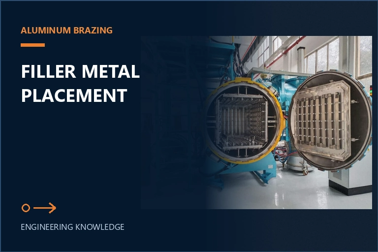
Aluminum vacuum brazing filler metal placement should be treated as a controlled assembly characteristic, not as a last-minute consumable choice. Select clad sheet, foil, wire, rings, shims, preforms or a qualified paste route from the joint geometry and production method; define where the filler starts, how much is present, how it is retained during loading, and which inspection evidence proves repeatable flow without starving one joint or flooding another.
Make filler placement a controlled design and assembly variable
Start with the joint drawing and its function. Record the base alloys, temper, product form, joint type, overlap or contact area, permitted clearance, service requirement, leak-tightness requirement, access for filler placement and inspection method. The filler designation alone does not define a usable brazing process. The drawing must also establish where filler is allowed, where it is prohibited, how the assembly is oriented in the furnace and which features can drain, trap or redirect molten metal.
Separate joint design from filler delivery while qualifying them together. A sound capillary joint still fails when the planned filler cannot reach the entrance, moves during handling or feeds several competing gaps unpredictably. Conversely, adding more filler does not correct an excessive or nonuniform clearance. Treat base material, surface preparation, gap, filler form, filler mass or dimensions, placement location, fixture restraint, thermal profile and inspection as one controlled system.
Create an assembly instruction that identifies filler form, lot, condition, storage, preparation, quantity, orientation and retention. Use photographs or controlled drawings for complicated assemblies, but preserve measurable requirements such as foil thickness, preform dimensions, ring position, clad-side orientation or paste deposit mass where those controls are part of the approved procedure. A visual aid should help the operator find the location; it should not replace a dimension, tolerance or acceptance rule.
Define who may change the placement method. Substituting foil for a preform, changing a clad sheet supplier, moving a ring to simplify assembly or using an adhesive to hold a part may alter flow, outgassing and final joint geometry. These are process changes that require engineering review and, when the qualified basis is affected, representative confirmation before routine production.
Choose clad sheet, foil or preforms from the joint geometry
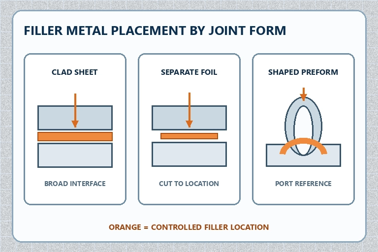
Clad sheet integrates a controlled filler-bearing layer with a parent sheet and is often useful when broad, repeated interfaces must receive filler consistently. Its effectiveness still depends on verified clad-side orientation, local contact, forming history, edge condition and the way the assembly heats. The production record should identify the clad product and orientation so a reversed sheet or mixed material cannot pass through assembly unnoticed.
Separate foil or shim stock can serve flat interfaces, local feed paths and development work where the filler needs to be positioned between components. Control the cut shape, thickness, cleanliness, wrinkles, edge protrusion and movement during fixture loading. A foil piece that bridges a designed vent or extends into a fluid channel can create a problem even when its total mass is correct. A narrow strip that shifts away from the joint entrance can leave part of the interface starved.
Rings, washers, wire forms and stamped preforms can place a repeatable amount around ports, tubes, bosses and other defined features. The preform must seat against a controlled reference and remain there through handling and thermal expansion. Avoid relying on an operator to judge an unmarked offset by eye. Use a shoulder, groove, stop, witness feature or documented gauge where the geometry permits, then verify that the retention feature does not block capillary access or become an unintended gap.
Paste or powder-binder systems can reach complex locations, but the qualified route must control composition, binder, mixing, deposit method, wet mass or volume, drying, handling and binder removal. Do not assume that a paste deposit is equivalent to a solid preform because both contain the same nominal filler alloy. The carrier can affect placement stability, contamination, vacuum behavior and the heating segment before brazing. Use the form that gives the joint a repeatable, inspectable feed path with the least uncontrolled variability.
Control filler quantity, location and retention before loading
Define filler quantity in a form that production can verify. Depending on the route, that may be clad product identity, foil dimensions and thickness, preform dimensions and count, wire length and diameter, or deposit mass and location. Record the measurement method and sampling frequency. A total assembly weight can be useful for gross confirmation but may not reveal that one joint has twice the intended amount while another has none.
Control the location with references tied to the part or fixture. Specify the distance from an edge, shoulder or port; the face on which a clad layer must appear; the direction a preform is installed; and the condition that confirms it is seated. For repeating arrays, use a placement map and part identity so missing, doubled or misplaced pieces can be found before the assembly becomes inaccessible. When vision inspection is used, qualify lighting, contrast, field of view and the feature that the system actually recognizes.
| Control surface | Production evidence | Failure prevented |
|---|---|---|
| Filler identity | Alloy, product form, supplier lot and storage status | Wrong filler or degraded material entering the load |
| Quantity | Clad identity, dimensions, count, length or qualified deposit mass | Starved joints, excessive fillets or blocked passages |
| Position | Drawing reference, placement map, gauge or vision check | Filler moving away from the intended capillary entrance |
| Retention | Fixture feature, approved tack method or handling verification | Shift during transport, loading or thermal expansion |
| Final assembly | Part identity, orientation, fixture identity and pre-load inspection | A correct subassembly entering the furnace in the wrong load state |
Retention methods need their own approval. Mechanical capture, grooves, tabs and fixture pressure can be effective when they do not alter the gap or block flow. Temporary binders or adhesives require material control, deposit limits, drying and a heating route that removes them without displacing filler or contaminating the vacuum system. Tacking that locally melts or distorts filler must be reviewed against the joint procedure. Record abnormal handling, dropped assemblies and rework so production does not quietly restore a moved preform by an unqualified method.
Connect filler placement to heating, capillary flow and fixturing
Filler begins to move only when the local joint and filler reach the applicable process condition. Large thermal assemblies can contain thick manifolds, thin fins, dense cores and fixture contacts that heat differently. A preform near a rapidly heated surface can begin to flow while a remote interface is still below the intended condition. The qualification load should therefore relate filler location to part geometry, thermal mass, load orientation and the measured thermal history rather than treating the furnace setpoint as the joint temperature.
Use load thermocouples or another approved measurement method where the procedure requires evidence from representative positions. Select attachment and routing methods that do not create a heat sink, open the joint or interfere with filler movement. Preserve position identity so a temperature record can be compared with fillet appearance, leak result, sectioned evidence or another acceptance outcome. Do not move sensors between development runs without documenting the reason and the new relationship to the joint.
Fixture design must hold the intended geometry while allowing predictable thermal expansion and filler access. Excessive restraint can close one region and open another; insufficient support can let a core, plate or port move before the filler solidifies. Confirm contact points, spring or dead-weight features when used, fixture material, cleanliness, orientation and service condition. A fixture that has warped or accumulated residue may change filler flow even when the recipe and filler quantity are unchanged.
Evaluate gravity and drainage in the actual furnace orientation. Flow marks, excessive external fillets or material inside a channel can indicate that the filler supply, local gap, thermal balance or assembly orientation needs review. Do not correct every incomplete fillet by adding filler. First determine whether the joint entrance was open, surfaces were prepared, the filler remained in place, the region reached the qualified thermal condition and the fixture maintained the intended clearance.
Qualify inspection, acceptance and change control by joint location
Define acceptance before the first production trial. The plan may include external fillet review, leak testing, dimensional inspection, pressure testing, sectioning, metallography, radiography or other methods selected for the joint class and service requirement. No single method is universally sufficient. Connect each inspected feature to the drawing location, filler placement, fixture position and cycle record so a result can identify a local mechanism rather than only label the whole load acceptable or rejected.
Use development and qualification assemblies that represent the production variation that matters: material lots, clad product, largest and smallest thermal masses, dense and open flow paths, center and edge load positions, fixture condition and normal handling. Record filler quantity and location before loading. After brazing, compare results by position. A favorable average leak rate or yield can hide a repeat weak location that points to a placement or thermal-balance problem.
Control rework as a new joining event. Adding filler to an incomplete joint, reheating a previously brazed assembly or grinding an excessive fillet can alter geometry, local metallurgy and inspection access. The rework instruction should define eligibility, preparation, additional filler form and amount, thermal exposure, inspection and disposition. Preserve the original nonconformance and evidence; otherwise the organization loses the information needed to improve the production route.
Set requalification triggers for changes in base or clad material, filler product, supplier, foil thickness, preform tooling, paste formulation, binder, fixture, load map, furnace, usable work zone, thermal program, vacuum condition, sensor method or acceptance requirement. Use a risk-based representative confirmation when the change can affect filler delivery or joint formation. Routine records should make the qualified state visible enough that a purchasing or assembly substitution cannot occur unnoticed.
Match the furnace configuration to the filler-placement plan
SYNHTE's Vacuum Brazing Furnace Systems include the High Vacuum Aluminum Brazing Furnace for batch aluminum heat exchangers, cold plates, condensers, evaporators, manifolds and related thermal assemblies. The current product pages identify filler flow, thermal balance, fixture repeatability, usable work zone, loading and production records as configuration inputs. These equipment functions support a qualified placement method but do not replace the joint and assembly procedure.
Prepare the assembly drawing, base and filler alloy, filler form, largest fixture envelope, load mass, thermal profile, production volume and acceptance requirements before requesting a configuration. Ask how the proposed work zone, heating zones, vacuum system, loading access, cooling route, controls and batch records will support representative joint locations. When the process is still being developed, a controlled vacuum brazing service discussion can help define trials and evidence before the equipment scope is frozen.
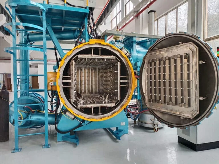
Include filler-placement evidence in factory and site acceptance planning only to the extent agreed for the project. Equipment tests can verify furnace functions, controls, alarms, vacuum behavior and thermal evidence under defined conditions. Customer-part process qualification remains a separate responsibility unless representative loaded trials and acceptance criteria are explicitly included. Keeping these boundaries clear prevents a machine capability check from being mistaken for proof that every production joint and filler route is qualified.
High Vacuum Aluminum Brazing Furnace
The SYNHTE batch aluminum brazing platform is configured around the assembly envelope, fixture, filler system, thermal balance, production load and acceptance plan. Furnace selection should follow a documented joining route, because heating zones, usable work zone, loading access, cooling and production records must support the qualified filler-placement method.
What to include in your enquiry
- Exact material, incoming condition and governing drawing or specification
- Part, interface, fixture, stack and production-load drawings
- Required process outcome, acceptance methods, limits and sample locations
- Current process route, fixed variables, development questions and known risks
- Batch volume, data-retention needs, utilities, site interfaces and delivery requirements