
Vacuum Brazing Diamond Tools: Qualification Controls for Joint Integrity

Vacuum brazing diamond tools requires qualification of the complete material-and-process system: abrasive, substrate, filler, surface preparation, joint geometry, fixturing, load arrangement, vacuum cycle, thermal exposure, cooling, and acceptance testing. Joint integrity must be demonstrated with traceable, production-representative evidence rather than a furnace temperature alone.
Define the diamond-tool system that must be qualified
Begin with the tool's required function and failure risks. Record abrasive retention, exposure or protrusion requirement, tool-body dimensions, runout or balance limits, allowed surface condition, operating load, inspection method, and the destructive or performance test that governs release. Separate product requirements from development observations. A visually continuous braze line may still hide a weak interface, while a darkened surface does not by itself identify the cause of a failure.
Create a controlled bill of process. Identify abrasive lot and classification, substrate lot and heat-treatment condition, filler batch and physical form, cleaning materials, time limits after preparation, assembly method, fixture material and contact points, furnace and hot-zone identity, approved load map, cycle revision, and acceptance plan. This record makes later deviations traceable and prevents a successful trial from becoming an undocumented shop recipe.
Control material, surface preparation, filler placement and fixturing
Surface preparation must create a repeatable starting condition without damaging the abrasive or changing the intended joint geometry. Define how the tool body is machined, cleaned, dried, handled, and protected before assembly. Record allowable storage time and re-cleaning rules. Oils, polishing compounds, fingerprints, loose abrasive, oxide, and cleaning residue can change wetting or produce gas during heating. Verification should focus on the controlled method, not a subjective statement that parts looked clean.
Filler application needs the same discipline. Control alloy identity, form, amount, placement, coverage, and lot traceability according to the approved procedure. More filler is not automatically safer: excess material can move, bridge unwanted areas, alter abrasive exposure, or create a geometry that is hard to inspect. Too little or discontinuous placement can leave an incomplete interface. Filler-system selection must be qualified for the specific diamond, coating, substrate, joint geometry, and service requirement.
Fixturing should locate the abrasive and tool body through heating while avoiding contamination, local shielding, uncontrolled pressure, and differential movement. Verify contact materials and release methods. Qualification traceability should continue from incoming materials and preparation through assembly, thermal processing, and final acceptance.
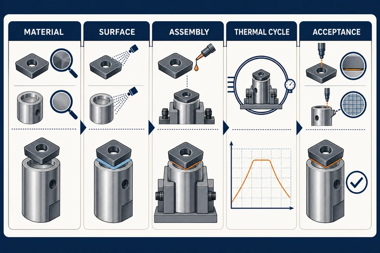
Build a controlled vacuum-brazing thermal window
The thermal cycle must allow the selected filler system to form the intended interface while limiting unnecessary exposure of the diamond, substrate, and fixture. Treat ramp rate, temperature distribution, time in the active range, load thermal lag, vacuum behavior, any approved atmosphere step, and cooling as connected variables. Controller temperature alone does not prove the temperature or time experienced by the most shielded tool position.
Use development trials to relate cycle records to joint evidence. Place sensors or witness items according to an approved method that does not create a false thermal condition. Monitor pressure trends and alarms for signs that the load, cleaning method, filler, or fixture releases more gas than expected, but do not diagnose a pressure feature from one signal alone. Compare it with the load map, furnace condition, visual evidence, and repeat trials.
Avoid copying a temperature and hold time from another diamond-tool system. Diamond type, surface treatment, filler chemistry, substrate, section mass, joint design, and furnace heat transfer can change the useful window. The appropriate target comes from the approved material system and test evidence. Fresh manufacturing research on brazed diamond tools continues to examine process variables and tool performance, reinforcing the need to qualify the exact combination rather than treating vacuum brazing as one fixed recipe.
Map acceptance evidence to load position and failure mode
Preserve tool position in the furnace load. Sample edge and center, top and bottom, or exposed and shielded locations according to the actual fixture and heat-transfer pattern. If the batch contains different tool sizes, identify the thermally light and heavy groups. A pooled average can hide a weak region that repeats every cycle. Position-resolved results are also more useful when adjusting fixture spacing or sensor placement.
Acceptance should combine nondestructive and destructive evidence appropriate to the product. Examples may include visual coverage against an approved standard, dimensions and runout, abrasive exposure, joint continuity by an applicable inspection method, retention or mechanical tests, metallographic sectioning, and a controlled cutting or wear test. The governing drawing, customer specification, or validated internal procedure must define the method, limit, and sample count.
| Evidence area | Question answered | Traceability needed |
|---|---|---|
| Incoming material | Were the abrasive, substrate and filler the approved system? | Lot, condition and supplier certificate where required |
| Assembly | Were placement, amount and fixture geometry repeatable? | Assembly record, fixture ID and representative image |
| Cycle | Did each load region receive the qualified thermal history? | Furnace, recipe, load map, sensors and raw cycle record |
| Product result | Did the joint and tool meet functional acceptance? | Inspection, destructive test and performance result by position |
When a tool fails, preserve the failure surface, original load position, cycle record, material lots, and fixture record before changing the process. Distinguish abrasive fracture, interface separation, filler discontinuity, substrate movement, contamination, and service overload. Corrective action should follow evidence. Raising temperature or adding filler without identifying the failure mechanism can trade one defect for another.
Match furnace capability to the diamond-tool qualification plan
SYNHTE's Vacuum Brazing Furnace range includes a High Temperature Vacuum Brazing Furnace for diamond and superhard-material applications. Equipment selection must still be qualified for the proposed tool, filler system, fixture, load, and cycle.
Discuss usable hot-zone dimensions, hot-zone material compatibility, temperature-uniformity evidence, vacuum-system configuration, sensor access, load support, cooling control, recipe security, data export, and maintenance provisions. Share the abrasive and substrate description, filler form, tool and load drawings, fixture concept, process window under investigation, acceptance methods, production volume, and facility constraints. If the process is still in development, state which variables are fixed and which require trials.
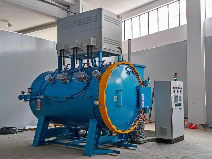
High Temperature Vacuum Brazing Furnace
This furnace family supports high-vacuum brazing with configurable hot-zone and programmable-cycle control for diamond and superhard-material tools. Final process qualification remains application-specific.
What to include in your enquiry
- Material or abrasive system, starting condition and controlling specification
- Part, joint, fixture and representative production-load drawings
- Current process route, fixed variables and development questions
- Required properties, dimensions, inspection methods and acceptance limits
- Typical batch volume, throughput target, utilities and site constraints