
MIM Debinding Binder-Vapor Management: Traps, Gas Flow and Qualification
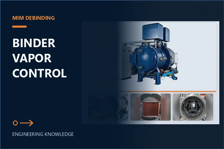
MIM debinding binder-vapor management should be qualified as a complete material-removal path. Define the feedstock and residual binder entering the furnace, control heating and process gas so vapor leaves the parts without damaging them, collect condensable fractions before they reach the pumps, inspect and clean every trap on an evidence-based interval, and link final part results to batch loading, pressure history and trap condition.
Define the binder inventory entering the furnace
Start with the exact feedstock and upstream route. Record the metal powder or alloy, binder system, molded-part mass, green density, wall-section range, part geometry, gate and weld-line concerns, storage condition and any solvent, catalytic or other pre-debinding step. The furnace does not receive a generic MIM part; it receives a known residual binder inventory distributed through a specific pore network and load arrangement.
Estimate and verify the residual mass that the furnace stage is expected to remove. The value should come from the qualified feedstock and upstream process rather than an assumed percentage. Include the number of parts, total green mass, prior mass loss and the permitted variation between loads. This inventory supports trap sizing, recipe limits and cleaning intervals. It also helps distinguish a material or upstream-debinding change from a furnace problem.
Define the quality risks that vapor management must protect against. Rapid or nonuniform removal can contribute to blistering, cracking, distortion or internal damage; binder residue or uncontrolled carbon-bearing species can alter surface and chemistry; carryover can foul lines and pumps. These mechanisms depend on binder chemistry, part thickness, permeability, setter contact, load density, gas flow and pressure history. Do not assign a universal heating rate or pressure recipe without development evidence for the actual system.
Engineer a visible, serviceable binder-vapor path
Binder products must leave the part, move out of the hot zone, pass through the intended collection stages and reach the pumping system without uncontrolled condensation in inaccessible piping. Map this path from the load and graphite box or process enclosure through collection boxes, cooled surfaces, valves, traps, Roots-pump section and backing-pump section as applicable to the delivered furnace. Identify which zones are heated, cooled, drained, opened and cleaned.
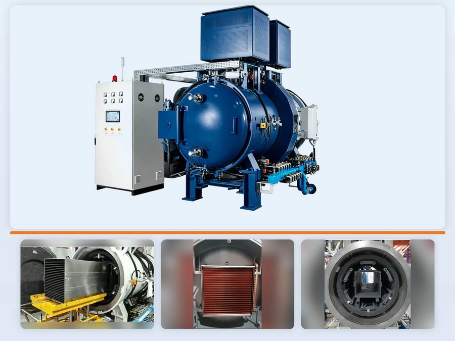
Staged collection is valuable because different binder fractions can condense under different conditions. The live SYNHTE MIM furnace page describes three water-cooled collection boxes and four sequential cold-trap sections before the vacuum pumps. That product architecture establishes a defined collection path, but its performance still has to be confirmed for the selected binder chemistry, residual mass, recipe and maintenance interval. A trap count alone does not prove capture under production conditions.
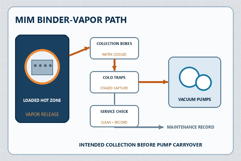
Make each service point inspectable and traceable. Record trap identity, orientation, connection, cooling condition, empty or clean baseline, collected mass or condition when useful, cleaning method and release status. Inspect pipe sections where temperature transitions can create unintended deposits. If operators cannot reach or verify a surface, the maintenance plan should explain how blockage or carryover will be detected before vacuum performance or product quality is affected.
Coordinate gas flow, pressure and heating with material removal
Debinding control is a coupled relationship. Heating changes binder mobility and vapor generation; pressure and process-gas flow influence transport away from the part; load spacing and setter contact shape the local path; trap temperature and conductance affect where material condenses. Define which variables are commanded, which are monitored and which indicate that vapor generation is exceeding the qualified removal capacity.
The SYNHTE MIM furnace page describes isolated internal and external gas inlet paths for its graphite-box configuration. That feature can help separate process-gas functions, but the production route must still define gas identity, purity, flow, pressure, exhaust handling, valve sequence and safety logic. Confirm where gas enters relative to the parts and where vapor exits. A displayed total flow does not prove that every loaded region receives the intended transport condition.
| Control surface | Evidence to retain | Release question |
|---|---|---|
| Material input | Feedstock, residual binder, green mass and upstream state | Was the vapor load inside the qualified envelope? |
| Transport condition | Heating response, pressure, gas identity, flow and load map | Could vapor leave representative parts without damage? |
| Collection system | Trap condition, cooling state, deposits, cleaning and carryover checks | Was binder collected in the intended serviceable locations? |
| Final result | Mass change, appearance, dimensions, density, chemistry or other required tests | Did the complete route produce the specified outcome? |
Use the applicable material procedure to establish the process window. Avoid interpreting a smooth pressure curve as proof of complete debinding, because a stable instrument trace can coexist with residue inside a thick section. Conversely, a pressure response may reflect expected vapor evolution rather than a leak. Correlate trends with load mass, part geometry, trap condition and final evidence before changing the recipe or repairing vacuum hardware.
Qualify a representative production batch
Choose qualification loads that represent the intended production range. Include the thickest or slowest-debinding geometry, relevant thin or fragile features, normal setter contact, maximum planned nesting density, center and edge locations, and the highest justified residual binder mass. If multiple feedstocks or upstream debinding routes will share the furnace, demonstrate why the challenge load represents each one or qualify separate envelopes.
Retain position identity. Record tray, layer, center, edge and other risk-based locations so mass loss, dimensions, density, appearance or destructive evidence can be traced back to the load. A small witness placed beside a dense production stack may confirm furnace exposure but cannot prove transport inside a part whose section and pore path it does not reproduce. Representative evidence must share the mechanism being qualified.
Review the complete cycle record: material and batch identity, pre-debinding state, green and residual mass where required, load map, setter and support, recipe revision, pressure history, process-gas events, heating response, alarms, interruptions, trap condition, collected material observations, cooling and final inspection. Define the disposition for a deviation before qualification begins. Repeating a load without protecting the original evidence can hide the mechanism that needs correction.
Build acceptance from the drawing, material standard and process plan. Depending on the part, evidence may include mass change, dimensions, density, chemistry, carbon or oxygen control, surface condition, porosity, mechanical properties and defect inspection. Not every test applies to every MIM route. Each selected method should answer a stated risk, use a defined sample location and have an approved limit.
Set cleaning limits and requalification triggers
Do not base trap cleaning only on elapsed calendar time. Establish an initial interval from qualified binder mass, batch count, observed deposits, pressure behavior and supplier guidance, then refine it with production evidence. Record the condition of each collection stage separately because deposits may not distribute evenly. Define the maximum allowed loading or condition, who may release a cleaned assembly and which parts or seals must be replaced rather than reused.
Use a controlled cleaning method compatible with the collected material, trap construction and site environmental and safety requirements. Binder residues and cleaning agents can create exposure, fire, waste or cross-contamination risks. Follow the feedstock safety data, equipment instructions and plant procedures. After reassembly, verify orientation, sealing, cooling connections, valves and vacuum integrity before returning the furnace to production.
Trend evidence that can reveal carryover or restriction: pump-down behavior, pressure response during debinding, trap deposits, line inspection, pump condition, unexplained surface change, carbon-related results and recurring location-specific defects. Do not diagnose from one signal alone. A slower pump-down could indicate deposits, a leak, pump condition or a different material load; use the established diagnostic sequence and the current batch record to separate the possibilities.
Define engineering review or requalification after a feedstock or binder change, altered upstream debinding, increased residual mass, thicker section, new nesting pattern, changed gas route, trap or pipe modification, cooling change, revised heating or pressure program, major pump service, repeated carryover or unexplained product failure. Written triggers protect the qualified envelope from gradual expansion without supporting evidence.
Match the furnace to the binder and production route
SYNHTE's Vacuum Sintering Furnace Systems include the MIM Vacuum Debinding & Sintering Furnace. The current product page describes integrated debinding and sintering, staged wax collection and isolated gas-flow paths. Those features provide a configuration basis, but the selected system must be reviewed against the actual feedstock, upstream route, residual binder, load density, final chemistry and maintenance plan.
Share the material and feedstock supplier, binder chemistry or processing guide where available, green-part and fixture drawings, wall-section range, upstream debinding method, residual mass per load, target batch size, atmosphere, required sintering result, inspection plan, production volume, exhaust and utility conditions, cleaning constraints and data-retention needs. Ask how the proposed collection stages, gas path, hot zone, pumps, cooling and controls support those inputs.
Put evidence expectations into the technical agreement: process and instrument diagrams, vapor-path and trap description, service access, approved materials, control sequence, alarm logic, factory test basis, representative material trial, cleaning procedure, spare parts, training and site acceptance. If the final feedstock cannot be used during factory testing, define what substitute evidence is acceptable and which site trial will close the qualification gap before routine production.
MIM Vacuum Debinding & Sintering Furnace
The MIM furnace platform combines controlled debinding, staged binder-vapor collection, process-gas management and sintering in one configured route. The applicable trap, gas and maintenance plan must be qualified against the actual feedstock, upstream debinding state, load and acceptance criteria.
What to include in your enquiry
- Exact material, incoming condition and governing drawing or specification
- Part, interface, fixture, stack and production-load drawings
- Required process outcome, acceptance methods, limits and sample locations
- Current process route, fixed variables, development questions and known risks
- Batch volume, data-retention needs, utilities, site interfaces and delivery requirements