
Hydrogen Furnace Dew Point and Oxygen Control: Qualification Guide
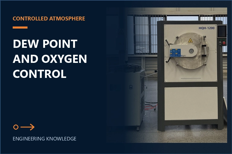
Hydrogen furnace dew point and oxygen control must be qualified as a complete atmosphere path, not as one gas-certificate value. Define the material and surface result, identify where moisture and oxygen can enter, sample at locations that represent the delivered gas and furnace exhaust, verify purge-to-process transitions, correlate atmosphere records with representative load results, and set maintenance and requalification rules for every change that can alter the gas path.
Define the material and surface result before setting gas limits
Begin with the workpiece and its required result. Record the alloy, powder or compact chemistry, incoming oxide condition, binder or lubricant history, surface-finish requirement, dimensional requirement and the property or reaction that the atmosphere must support. Hydrogen may be used for selected reduction, protective-atmosphere heat treatment or sintering routes, but the acceptable moisture and oxygen condition is material- and process-specific. A limit copied from another alloy, furnace or laboratory can be either unnecessarily restrictive or technically inadequate.
Separate the process objective from the measurement. The objective may be to limit oxidation, support a defined reduction response, protect color, avoid a surface film that affects a later operation, or maintain a qualified chemistry window. Dew point is one way to express moisture content under defined conditions, while an oxygen analyzer reports a different part of the atmosphere state. Neither value proves the final material result by itself. Qualification must connect the instrument reading, sampling location, thermal exposure and representative part evidence.
Write an atmosphere specification that identifies gas composition, gas-supply quality, measurement basis, sampling point, operating phase, analyzer range, calibration method, alarm or hold response and acceptance evidence. Define whether the limit applies at the cylinder or bulk source, the furnace inlet, the hot-zone outlet, the exhaust or more than one location. Also define the condition under which a recorded value is considered stable. Without those details, two teams can report the same number while measuring different gas paths.
Hydrogen service requires a site-specific engineered safety system. Atmosphere-quality work does not replace purge verification, ventilation, gas detection, exhaust treatment, safe-state logic, operator training or local regulatory review. Keep process-quality limits and safety permissives clearly identified, then test how they interact so an instrument fault cannot create an ambiguous operating state.
Map the complete atmosphere path and sampling locations
Trace the gas from the approved source to the point where it leaves the process. Include the source manifold, regulators, purification or drying equipment when supplied, distribution piping, flexible connections, mass-flow controller or rotameter, valves, furnace inlet, chamber or retort, hot zone, workpiece load, exhaust line and analyzer take-offs. Mark every location where maintenance, material choice, a seal, a dead leg or ambient exposure can introduce moisture or oxygen.
Sampling location determines what the result means. A source-side sample can confirm delivered gas quality but cannot reveal moisture released by downstream piping, the chamber, fixtures or the load. An inlet sample can represent the gas entering the furnace yet miss reactions and outgassing inside the hot zone. An exhaust sample includes more of the process path, but its reading can be affected by sampling-line temperature, condensation, leakage, back diffusion, exhaust dilution and analyzer response time. Use the points that answer the qualification question and document the limitations of each one.
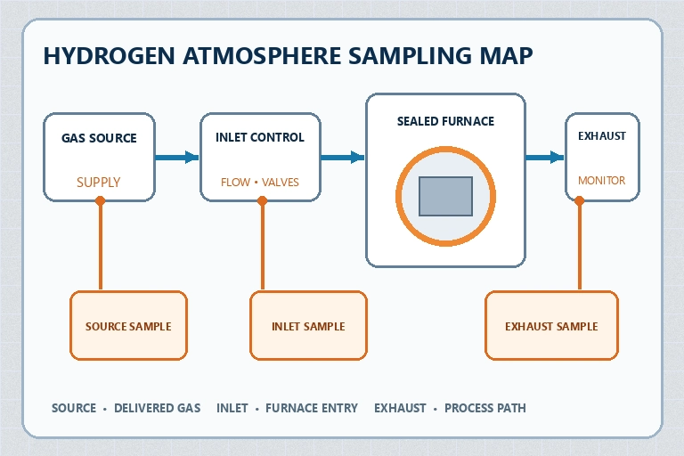
Design the sample line as part of the measurement system. Record its material, length, internal volume, connection method, isolation valves, filtration, flow control, heating or temperature control when required, discharge route and leak-check method. A cold or contaminated line can hold moisture and delay stabilization; a leaking connection can make an oxygen reading appear to be a furnace problem. Locate analyzers where they can be calibrated, isolated and serviced without defeating the approved gas or exhaust arrangement.
Give every analyzer point a tag that matches the piping diagram, control screen and batch record. If one portable instrument is moved among locations, control the connection and stabilization procedure and retain the actual sampling point with each result. This traceability makes a change in reading diagnosable instead of turning it into an argument about which valve or tube was used.
Qualify purge, transition and steady-state atmosphere evidence
A production record should show how the furnace moved from its initial condition to the approved process atmosphere. Define the precondition for starting the purge, the verified conditions that permit hydrogen admission, the gas-transition sequence, analyzer response expected during the change, the condition that establishes process readiness and the response to a failed or unstable transition. These steps must come from the engineered system and site safety review; do not copy purge times or permissives from another installation.
Distinguish line conditioning from furnace conditioning. New piping, opened connections, a serviced chamber, replaced insulation, a wet fixture or a load with higher surface area can extend the time needed to reach a repeatable atmosphere. Record which equipment was opened, how it was returned to service and whether an empty-furnace conditioning cycle was required. If the process depends on a dry atmosphere at temperature, confirm that the measurement remains meaningful through the relevant thermal phase rather than only before heating.
Analyzer lag should be characterized during commissioning. Introduce a controlled, approved change or use the supplier's verification method to determine the delay from the sampling point to the displayed and recorded response. Include sample-line volume, flow and instrument filtering. A slow display can create the impression that the furnace is stable after the actual gas has changed, or keep a batch waiting after the atmosphere has recovered. Use the measured response to set data-review rules without weakening safety logic.
Define steady state by more than one isolated reading. Require the relevant gas flow, pressure, furnace condition, analyzer status and time trend to remain inside the approved window. Record alarm, hold and stop behavior for loss of sample flow, analyzer fault, gas interruption, exhaust fault or a value outside the process limit. If the control system does not use the analyzer as a permissive, make the operator and quality review responsibility explicit.
Separate dew point, oxygen and leak-tightness evidence
Use each signal for the question it can answer. Dew point or another validated moisture expression can indicate water content at the sampling point under the stated pressure and temperature basis. Oxygen measurement can reveal oxygen-bearing contamination at its sampling point. Leak testing examines system integrity through a different method and condition. A good leak-rate result does not prove that fixtures or a loaded part are dry, and a favorable inlet dew point does not prove that the exhaust path contains no air ingress.
Interpret trends with the process state. Moisture can come from the gas source, distribution system, sample line, chamber surfaces, insulation, fixtures, binders, cleaning residue or the parts themselves. Oxygen can come from residual air, leakage, an opened connection, analyzer sampling faults or oxygen-bearing material reactions. Compare the timing of the change with valve events, heating, load outgassing and maintenance history before adjusting the recipe or replacing equipment.
| Evidence surface | What it can establish | What it cannot prove alone |
|---|---|---|
| Gas-source certificate or source sample | Quality delivered at the approved source boundary | Condition after distribution piping, furnace exposure and load outgassing |
| Inlet moisture and oxygen sample | Condition of gas presented to the furnace inlet | Atmosphere around all workpieces or at the exhaust |
| Exhaust or process-path sample | Combined effect of furnace path, load and sampling arrangement | Exact source of a deviation without supporting evidence |
| Leak-tightness test | Integrity under the defined test method and condition | Moisture release, gas purity or material acceptance |
| Representative part result | Whether the qualified route produced the specified outcome | Which atmosphere variable caused a later deviation |
Build the release decision from the combined evidence. A stable atmosphere trace should be linked to gas-lot identity, analyzer status, flow and pressure records, thermal history, load map and final inspection. When a value is outside the approved condition, protect the original record and review the complete path. Changing purge duration, gas flow and thermal program together may recover the next load, but it removes the evidence needed to identify the controlling mechanism.
Qualify a representative load and the measurement system
Choose loads that represent the planned production envelope. Include the highest justified surface area, relevant binder or lubricant condition, thick and thin sections, the normal fixture, maximum nesting density and center, edge or gas-flow positions that may experience different exposure. If different materials share the furnace, define separate qualified windows unless evidence shows that one challenge load represents the important moisture, oxygen and reaction risks of each route.
Retain position identity for test pieces and production parts. Surface appearance, mass change, chemistry, density, dimensions, mechanical response or other acceptance tests should be tied to the location and process record that produced them. A small coupon near the analyzer outlet may confirm one exposure condition but cannot represent a shielded feature or dense tray whose gas exchange and surface area are materially different.
Qualify the analyzer system with the instrument supplier's approved method. Record instrument identity, range, calibration or verification standard, sample-flow condition, zero and span response where applicable, maintenance state, alarm behavior and data integration. Confirm how the system handles an out-of-range value, lost sample flow, sensor end-of-life warning and communication failure. Avoid treating a numerical display as valid simply because it is available in the batch record.
Run enough confirmation work to include normal variation in source gas, production loading and furnace condition. Define who reviews atmosphere evidence, what constitutes an acceptable trend, how deviations are contained and how long the records remain available. Qualification is complete only when operators, process engineering and quality personnel can reach the same release decision from the retained data.
Match furnace configuration to the atmosphere-control plan
SYNHTE's Vacuum Sintering Furnace Systems include the Hydrogen Atmosphere Tube Furnace. The current product page describes vacuum preparation, metered gas entry, dual-zone temperature control and monitored exhaust ignition. It also states that gas purity, dew point and the thermal process are application inputs. Those features establish a configuration basis, while the actual gas train, analyzer points, limits and safety functions must be engineered for the material and site.
Share the material specification, incoming oxide or binder condition, part and fixture drawings, load mass and pattern, gas composition and source, required moisture and oxygen basis, planned sample locations, thermal program, exhaust arrangement, acceptance methods, production volume, data-retention needs and applicable site safety requirements. Ask how the proposed valves, flow control, chamber, retort, vacuum preparation, sample interfaces, exhaust handling and controls support the complete qualification path.
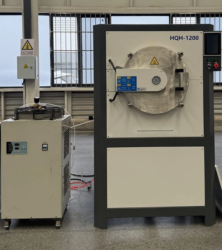
Put evidence requirements in the technical agreement: gas and purge schematic, analyzer interfaces, control narrative, alarm and safe-state logic, calibration access, sample discharge route, material compatibility, factory test basis, representative trial, training, maintenance instructions and site acceptance. If the final production gas or load cannot be used during factory testing, define the substitute evidence and the site trial that will close the remaining qualification gap before routine production.
Set engineering review or requalification triggers for a new gas supplier or composition, changed purifier or regulator, opened distribution line, modified sample location, replaced analyzer technology, changed retort or seal, new fixture material, increased load surface area, changed binder condition, altered flow or pressure program, revised exhaust hardware, major maintenance or unexplained surface result. Written triggers keep the atmosphere window from drifting through small undocumented changes.
Hydrogen Atmosphere Tube Furnace
The SYNHTE hydrogen atmosphere tube furnace combines vacuum preparation, metered gas entry, dual-zone heating and monitored exhaust handling in one configured platform. The applicable gas train, analyzer locations, transition logic and acceptance limits must be engineered around the material, gas source, process route and site safety requirements.
What to include in your enquiry
- Exact material, incoming condition and governing drawing or specification
- Part, interface, fixture, stack and production-load drawings
- Required process outcome, acceptance methods, limits and sample locations
- Current process route, fixed variables, development questions and known risks
- Batch volume, data-retention needs, utilities, site interfaces and delivery requirements