
Aluminum Vacuum Brazing Soak Time: Qualify the Loaded Thermal Window
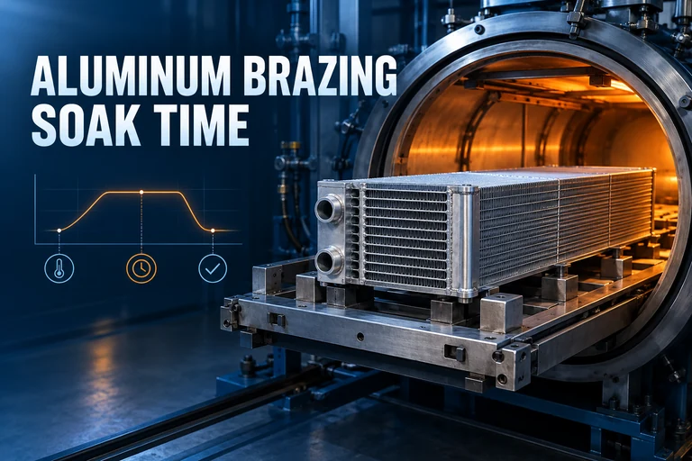
Aluminum vacuum brazing soak time should begin when the slowest qualified load location enters the approved brazing window—not merely when a furnace controller reaches its programmed plateau. The required hold is therefore a result of the real load, joint system and acceptance evidence. Core thickness and load weight can help define a trial matrix, but they cannot replace representative loaded thermocouples and finished-part verification.
This distinction matters for plate-fin heat exchangers, cold plates and other dense aluminum assemblies. Their exposed edges may respond quickly while shielded joints near the center continue to lag. If the clock starts too early, filler may not flow consistently at the slowest locations. If the cycle is extended without evidence, the hottest areas remain exposed longer than necessary, increasing the risk of dimensional change, local erosion or other process-specific damage. The objective is not the longest possible hold; it is a repeatable thermal window that produces acceptable joints throughout the qualified load.
Start the soak from the load—not the controller
The controller thermocouple is essential for operating the furnace, but it normally represents a furnace control zone rather than the coldest joint in a production load. A programmed plateau indicates what the control system is commanding and sensing at its own location. It does not, by itself, establish that every heat-exchanger core, fixture contact and shielded joint has reached the same state.
Define the soak-start event in the approved procedure. A defensible rule may require every designated load thermocouple, or a specified set of representative locations, to enter the qualified temperature band before the hold clock begins. The exact band, number of sensors and acceptance logic must come from the applicable filler system, material condition, drawing, customer requirement and qualification plan. Avoid copying a time from an unrelated core simply because its external dimensions look similar.
Also distinguish three records that are often confused: furnace temperature-uniformity evidence, controller performance during the cycle, and workpiece-temperature evidence from a representative load. A furnace survey can demonstrate the equipment's calibrated uniformity under its defined test conditions. It does not automatically predict the internal thermal lag of a densely stacked production load. Loaded thermocouples answer that different question.
Why core mass, stacking and radiation view change thermal lag
Vacuum heating depends strongly on radiation and on conduction through contacts within the load. An exposed face with a clear view of the hot zone can heat differently from a joint buried behind fins, side plates, fixtures or neighboring cores. Adding more nominal mass is only one change; redistributing that mass can alter view factors and conduction paths even when the total weight is unchanged.
Spacing is therefore a process variable, not just a loading convenience. A tightly packed row can shield interior surfaces, while a heavy fixture can absorb energy and delay the assembly it supports. Position within the usable work zone, distance from surrounding shields, tray design, contact area and orientation of the broad faces all influence the lag pattern. A light but deeply shielded core may heat more slowly at a critical joint than a heavier core with better radiative exposure.
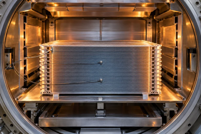
Use this physical map to choose measurement points. The hottest-looking outer surface is rarely the only position worth monitoring. Candidate slow locations often include the center of the densest core, a lower region coupled to a massive support, an area shadowed by another assembly and the rear or edge position that historically responds differently. The drawing and loading sketch should explain why each point represents a risk, rather than placing sensors wherever attachment is easiest.
Build a representative thermocouple and load map
A qualification load should reproduce the production conditions that govern heat flow. Record core part numbers, alloys and tempers where relevant, filler form, core dimensions, quantity, fixture identity, tray position, spacing, orientation and total loaded envelope. Photograph or sketch the arrangement so operators can repeat it. A weight entry alone cannot reconstruct where shielding occurred.
Place load thermocouples at positions selected from the thermal-risk review. Include likely cold points and at least one faster-responding comparison location. Attachment must be stable enough to follow the intended component rather than furnace radiation, yet it must not contaminate the assembly or create an unrepresentative thermal bridge. Document the sensor type, attachment method, channel, exact location and replacement criteria.
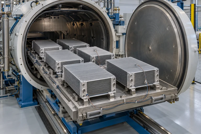
Run enough trials to separate a repeatable pattern from one unusual cycle. Compare the time at which each load channel enters the intended window, the spread between the first and last representative locations, the duration of exposure for the earliest location, furnace pressure behavior and the final part results. If a sensor detaches or produces an implausible trace, do not silently average it away; investigate the event and decide whether the run remains valid.
| Evidence | What it can show | Decision it supports | Common misuse |
|---|---|---|---|
| Controller trend | Zone response and program execution | Whether the furnace followed the intended recipe | Treating setpoint arrival as proof that the core center is ready |
| Loaded thermocouples | Thermal lag and position-to-position spread | When the defined load-based soak starts | Using one easy-to-heat surface sensor for every load position |
| Furnace uniformity evidence | Equipment performance under the survey conditions | Whether the furnace remains within its qualified equipment condition | Using an empty or survey load as a substitute for production-load mapping |
| Joint and coupon results | Whether the selected cycle produced the required joint outcome | The minimum acceptable thermal exposure for that qualified route | Judging the entire assembly from one accessible external fillet |
| Dimensional and leak results | Whether the completed assembly meets functional acceptance | Whether the selected window is acceptable as a complete process | Extending time after a thermal issue without checking distortion or overexposure |
Set the hold window between joint formation and overexposure
The lower boundary of the hold window is the exposure needed for the slowest relevant locations to produce acceptable joints. The upper boundary is the exposure beyond which the earliest or hottest locations, base material, filler reservoir, braze sheet, fixture or finished geometry no longer meets the process acceptance criteria. Both boundaries should be established with representative evidence; neither should be guessed from the controller trace alone.
Review joint formation using the methods required by the drawing or governing procedure. Depending on the product, the plan may include visual examination, metallographic sections, leak testing, pressure testing, mechanical tests, dimensional checks or destructive qualification samples. Do not describe one attractive fillet as proof that every internal joint is acceptable. Likewise, do not call a cycle safe merely because no obvious external melting is visible.
Time, temperature and vacuum interact. Extending a hold can change filler distribution and increase exposure of the earliest-heated areas; raising temperature to shorten a lag problem changes a different process variable. Treat either action as a controlled process change and verify the resulting joints and geometry. The qualified recipe should state the load-based start rule, target window, maximum exposure logic and response to a channel that fails to reach the expected condition.
Qualify normal, light and heavy production loads
Production rarely runs one identical load forever. Define load families from heat-flow behavior, not only from sales part numbers. A normal family might share core construction, orientation, spacing, fixture type and loaded envelope. A light-load variant can respond faster and may expose parts longer if it uses the same fixed program. A heavy or densely stacked variant may create a new cold location and delay the soak start.
Identify the operating envelope supported by evidence: minimum and maximum quantities, permitted positions, approved spacing, fixture versions and any empty positions that require thermal ballast or a different recipe. If one cycle is intentionally used for multiple families, demonstrate that the fastest family does not exceed its upper exposure boundary while the slowest family still meets its lower boundary.
Use production records to confirm that the qualified arrangement is actually being loaded. A clear traveler can record family, quantity, tray map, fixture ID, recipe revision and exceptions. Trend the lag between representative channels rather than recording only pass/fail. A gradual increase can identify sensor, fixture, hot-zone or loading changes before finished-part failures appear.
What changes require requalification or a controlled review?
A process remains qualified only inside its approved boundaries. Some changes clearly create a new thermal condition; others require an engineering review to determine whether existing evidence still applies. Establish that decision path before production pressure turns a temporary loading change into an undocumented new process.
| Change | Why it matters | Minimum controlled response |
|---|---|---|
| Core geometry, braze sheet or filler system | Joint mass, flow behavior and acceptable exposure can change | Review the qualification basis and run representative joint evidence as required |
| Quantity, spacing, orientation or tray position | Radiation view and the cold-point location may move | Compare with the approved load map; remap when outside its envelope |
| Fixture, support or thermal ballast | Contact conduction and absorbed thermal mass change | Document the revision and repeat loaded evidence where equivalence is not demonstrated |
| Hot-zone repair, sensor relocation or control revision | Equipment response or measurement relationship may change | Complete the required equipment checks and confirm representative load behavior |
| Acceptance requirement or customer specification | The previous evidence may no longer answer the required question | Update the plan before processing the affected order |
Specify the furnace around the qualified load
When comparing vacuum brazing furnace systems, provide the complete loaded envelope, intended core families, fixture mass, tray arrangement, measurement plan and acceptance route. Usable work-zone dimensions alone do not establish that a furnace can reproduce the required load response. Discuss the number and location of control zones, load-thermocouple capacity, data recording, recipe protection and how the loading arrangement maintains radiative access.
For aluminum heat-exchanger applications, a High Vacuum Aluminum Brazing Furnace provides the relevant equipment context for reviewing the all-metal hot zone, programmed heating stages and loaded temperature evidence. Equipment selection does not create the soak-time value automatically. The final process window must still be qualified with the user's alloys, filler system, fixture, load family and acceptance requirements.
Discuss the loaded thermal window
Share the core family, loading map, fixture and available temperature records. SYNHTE can review how furnace configuration, control zoning and load-temperature measurement fit the intended aluminum brazing qualification route.
What to include in a soak-time review
- Core drawings, alloy and temper, filler or braze-sheet system, and required joint acceptance.
- Normal, minimum and maximum load maps with quantity, spacing, orientation and fixture details.
- Existing controller and load-thermocouple traces, including sensor locations and attachment methods.
- Leak, dimensional, metallographic or other qualification results required by the governing specification.
- Planned production rate, handling route, recipe controls and changes expected between product families.
Send the application details to SYNHTE so the equipment discussion begins with the actual loaded process rather than a universal time formula.
Technical reference
- AWS C3.7M/C3.7:2011 (R2022), Specification for Aluminum Brazing — published scope covering minimum requirements for aluminum brazing fabrication, equipment, materials, process and inspection; the applicable contract and customer requirements remain controlling.