Vacuum Furnace Part Discoloration: A Root-Cause Troubleshooting Workflow
What discoloration can—and cannot—tell you
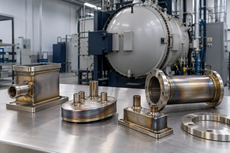
Bright parts leaving a vacuum furnace with straw, blue, gray or dark deposits immediately suggest oxidation, but appearance alone does not identify the source. A thin oxide, condensed pump oil, volatilized process residue and transferred fixture contamination can all change surface color. The alloy, prior surface finish, furnace temperature and viewing angle also change how a film looks. Treat color as a trigger for investigation rather than proof of a particular leak.
The most useful first question is not “What pressure should we use?” It is “When did the surface condition change?” If the pressure trace deteriorated during heat-up, investigate outgassing, trapped volumes and vacuum-train capacity. If a clean part becomes colored only after gas backfill or fan cooling, investigate gas purity, dew point, line purging and cooling-loop integrity. If the furnace runs normally but only certain load positions are affected, map the pattern against gas flow, fixture contact, cold surfaces and suspected local contamination.
| Observed pattern | First hypothesis | Evidence to collect |
|---|---|---|
| All parts darken during heat-up | Moisture, hydrocarbons, load outgassing or insufficient pumping | Pressure-time trace, empty-versus-loaded pump-down, recent cleaning and load changes |
| Color appears after backfill or fan start | Oxygen/moisture in gas, poor line purge, air ingress or exchanger leak | Gas certificate, point-of-use dew point/O₂, purge record and cooling-loop inspection |
| One side or one rack position is affected | Local gas path, cold surface, fixture transfer or localized leak | Load map, witness coupons, fixture history and leak-test location |
| Empty chamber is poor too | Seal, valve, gauge, pump, foreline or chamber contamination | Cold base pressure, rate-of-rise, isolation checks and gauge cross-check |
Build a phase map before changing the recipe
Save the complete cycle trace before resetting alarms or repeating the batch. Mark door closure, pump transitions, heat ramps, intermediate holds, peak temperature, partial-pressure steps, gas admission, fan start and door opening. Place the first abnormal pressure behavior and the first confirmed appearance change on the same timeline. If visual inspection is possible only after unloading, run a controlled witness-coupon study rather than guessing from the final color.
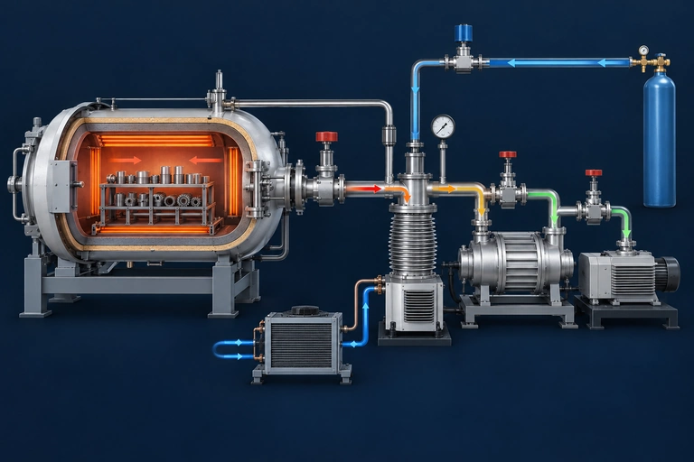
A useful phase map combines four channels: chamber pressure, temperature, valve/pump state and gas/cooling events. Add load identity, fixture identity and cleaning batch. A vacuum value by itself is incomplete because the same total pressure can contain very different fractions of water vapor, air, hydrocarbons or process gas. Likewise, an apparently normal controller trace does not prove that the load and chamber surfaces were clean.
Do not lengthen a hold or lower a pressure alarm simply to make the cycle complete. That can hide a developing leak or contamination source while exposing parts for longer. Preserve the failed-cycle evidence first; then change one controlled variable at a time.
Start with empty, coupon and production-load comparisons
Use a three-level comparison. First, establish the clean, empty-chamber pump-down and rate-of-rise behavior using the plant’s approved procedure. Second, run a clean witness coupon or representative inert load using an approved cycle. Third, repeat with the actual fixtures and production load. This sequence separates equipment behavior from what the load introduces.
- Empty chamber fails: investigate the pressure measurement, seals, valves, cooling circuits, foreline and pumps before blaming the product.
- Empty chamber passes but the clean coupon fails: investigate hot-zone deposits, oil backstreaming, cooling/backfill events and surfaces that release contamination only when heated.
- Coupon passes but production load fails: investigate part cleaning, blind holes, trapped liquid, porous fixtures, binder or stop-off residue, and load density.
- Only selected positions fail: preserve the location map. Swap positions or fixtures in a controlled trial to determine whether the pattern follows the part, fixture or furnace zone.
The coupon material and finish should be relevant to the suspected mechanism. A polished stainless coupon may reveal a thin film clearly, but it does not necessarily reproduce the reactivity of titanium, aluminum or a plated assembly. Define what the coupon can prove before using it as a production-release surrogate.
Use an evidence matrix for the main cause families
| Cause family | Typical evidence | Controlled check | Do not conclude from |
|---|---|---|---|
| Real air leak | Poor empty-chamber behavior, repeatable rate-of-rise change, localized helium response | Approved isolation and leak-detection procedure | One high pressure reading |
| Outgassing or virtual leak | Loaded cycle degrades; pressure improves with time/temperature; new blind volumes or porous tooling | Remove or dry suspected load elements and compare | Slow pump-down alone |
| Backfill gas contamination | Color appears after gas admission; point-of-use dew point/O₂ is abnormal | Verify cylinder/bulk source, regulator, line purge and point-of-use sample | Supplier certificate alone |
| Oil or chamber contamination | Film or odor, deposits on shields/valves, service event, cold-surface condensation | Inspect traps and foreline; clean/bake only under approved procedure | Part color alone |
| Cooling-water ingress | Water signature, unexplained moisture, cooling-circuit loss or leak response | Isolate and pressure/leak test the affected circuit safely | Wet-looking deposit alone |
| Premature unloading | Parts are bright before venting but color after hot air exposure | Verify actual load temperature and approved unload limit | Furnace thermocouple only |
This matrix is deliberately evidence-based. For example, a gas bottle labeled high purity can still deliver contaminated gas through a wet regulator or a line that was opened to air. A helium response at one flange is stronger evidence than a broad “vacuum is poor” impression, but it must still be evaluated with the detector setup, background, calibration and test mode documented.
Confirm leak location without contaminating the investigation
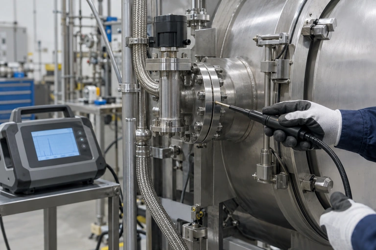
Helium mass-spectrometer leak detection is valuable when the furnace boundary, valve or cooling circuit is suspected. Use the furnace and detector manufacturer’s approved method, verify detector readiness with the correct reference leak, and record the test mode, background, response and exact probe location. A large helium background or indiscriminate spraying can obscure small signals and waste time.
Work systematically around door seals, feedthroughs, valve stems, instrument ports, removable flanges and service connections. Separate external leaks from internal valve bypass. Cooling jackets and heat exchangers may require a different approved configuration than the vacuum boundary. Never pressurize a circuit beyond its rated or site-approved limit, and follow lockout and gas-safety procedures.
After repair, repeat the same baseline test used before repair. A lower displayed pressure without a comparable test interval and configuration is not sufficient recovery evidence. For qualification-sensitive work, document the deviation, repair, verification and required representative load before production release.
Verify backfill gas at the point of use
Gas quality must be confirmed where it enters the furnace, not only at the supplier source. Check the correct gas connection, regulator condition, line integrity, purge sequence, point-of-use oxygen and moisture/dew point, and any change in cylinders or bulk supply. A line opened during maintenance can retain air and water even when the new gas source is within specification.
Relate the measurement to the approved process and material requirement; do not adopt a universal dew-point or oxygen limit from another furnace. Also distinguish nitrogen from argon suitability. The correct gas depends on alloy, temperature, cooling duty and specification. If discoloration begins only when the circulation fan starts, inspect the heat exchanger and recirculation path as well as the incoming gas.
Record the gas lot, sampling point, instrument ID, calibration status, sample pressure/flow and result. These details turn a one-time reading into traceable evidence and make future recurrence easier to compare.
Control cleanliness without spreading residue
Contamination can come from part-cleaning residue, fingerprints, stop-off, braze paste vehicle, lubricants, pump oil, dirty fixtures, insulation dust or deposits in cold regions. Review what changed before aggressive cleaning: a new solvent, longer storage, a porous fixture, pump service or a load with blind cavities may explain the event.
Use only approved cleaning agents and methods compatible with the hot zone, seals and plant safety rules. Do not introduce gasoline or an unapproved solvent into a vacuum furnace. When disassembly is necessary, protect clean surfaces, document component orientation and keep removed deposits available if laboratory analysis could help. A controlled clean-up or bake-out cycle should have a defined endpoint based on pressure behavior or other approved evidence—not simply a longer time.
If oil backstreaming is suspected, review pump condition, traps/baffles, valve sequencing, foreline pressure and shutdown behavior. Cleaning the chamber without correcting the transport mechanism invites recurrence.
Prove recovery before releasing production
A repair is complete only when the original symptom and the underlying process evidence both recover. Repeat the same empty-chamber baseline, leak or rate-of-rise check, gas-quality check and controlled coupon/load trial as applicable. Compare results with the last known-good cycle rather than with a newly relaxed limit.
Define appearance acceptance before the next run. Photographs should use consistent lighting, camera angle and clean reference samples; visual color alone may not prove metallurgical acceptance. Depending on the alloy and customer requirement, additional checks may include surface chemistry, residue analysis, hardness, metallography, braze-joint inspection or leak testing.
Minimum recovery record
- failed and recovery cycle traces with identical key milestones;
- empty, coupon and production-load comparison results;
- identified root cause and each controlled change;
- leak-test, gas-quality or cleanliness evidence as applicable;
- representative part inspection and release authority;
- preventive action, owner and recurrence-monitoring point.
SAE AMS2678 defines requirements and procedures for vacuum-atmosphere furnace brazing. The exact revision and customer specification must be identified in the process documentation. For vacuum heat-treatment contamination, ASM’s 2025 proceedings paper specifically identifies outgassing, backstreaming, leaks and particle generation as important sources of discoloration.
Review equipment and process evidence together
Recurring discoloration is rarely solved by selecting one larger pump in isolation. Review chamber volume, hot-zone materials, pump train, valve logic, instrumentation, gas delivery, cooling hardware, load contamination and the acceptance requirement as one system. See Vacuum Brazing Furnace Systems and the Vacuum Annealing Furnace for equipment context.
What to include in your enquiry
Share the alloy and surface finish, process type, failed and known-good cycle traces, the phase when color appeared, empty-chamber and loaded behavior, gas source and point-of-use readings, fixture/load changes, maintenance history and clear photos under consistent lighting.