High-Temperature Ceramic-to-Metal Joining: Processes and Development Trends
High-temperature ceramic-to-metal joining is a joint-system problem: the ceramic, metal, interlayer and geometry must work together during joining and throughout service. Vacuum brazing, solid-state diffusion bonding and transient liquid phase bonding offer different interface mechanisms. Select among them using wetting or contact requirements, reaction-layer stability, thermal-expansion mismatch and service-condition tests—not peak furnace temperature alone.
Start with the service duty and joint functions
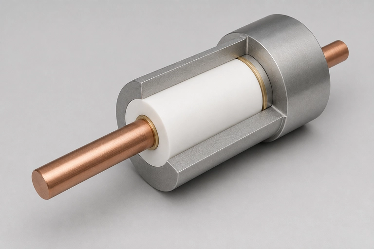
A ceramic feedthrough contains more than a ceramic-to-metal contact. The ceramic separates the central conductor from the metal housing, while the inner and outer joint regions can each form part of the vacuum boundary. Electrical isolation and sealing therefore need separate verification.
That functional approach also applies to ceramic tips, sensor housings and structural transitions. Record the actual ceramic grade, metal alloy, surface condition and geometry before choosing a process. Alumina, zirconia, silicon nitride and silicon carbide are not interchangeable substrates. Purity, porosity, surface finish and processing history can alter joining behavior even when the nominal material name is unchanged.
Define the temperature at the joint itself, including sustained exposure, short excursions and gradients across the assembly. Add the atmosphere, mechanical load, vibration, thermal cycling and any electrical or sealing duty. A ceramic placed at the hottest surface may connect to a metal region that remains cooler; assuming one temperature for the complete component can misdirect both materials selection and qualification.
Keep three temperatures separate: the joining temperature, the remelting or transformation limits of the completed interface, and the permissible service temperature under load. A furnace capable of a high peak temperature does not establish the last of these. Likewise, a room-temperature test of a brazed sample does not demonstrate resistance to creep, oxidation or repeated thermal shock in operation.
Compare three high-temperature ceramic-to-metal joining routes
Choose the interface mechanism before setting the furnace recipe. The presence of a liquid phase, the need for pressure and the final interface chemistry determine which route deserves a development trial. The following comparison is a selection framework, not a transferable processing schedule.
| Joining route | Interface mechanism | Selection question |
|---|---|---|
| Vacuum brazing | A compatible liquid filler wets prepared surfaces and solidifies in the joint. Active fillers or prior metallization provide a route to ceramic wetting. | Check wetting, reaction products, joint clearance and the braze phase at the actual service temperature. |
| Solid-state diffusion bonding | Prepared interfaces join through intimate contact and diffusion under a controlled thermal and loading cycle; an interlayer may be used. | Check pressure access, ceramic stress concentrations, surface quality, interlayer reactions and remaining voids. |
| Transient liquid phase bonding | A designed interlayer forms liquid temporarily; diffusion changes its composition so it can solidify during the hold. | Demonstrate completion of the intended transformation and the final joint phases; do not infer service capability from the initial interlayer melting point. |
Vacuum brazing: establish wetting first
A conventional filler that wets the metal may not wet an untreated ceramic. An active element such as titanium can promote a reaction at the ceramic surface, while suitable metallization offers another route to a brazeable surface. These alternatives require different surface preparation and material controls. A silver-based active braze is not automatically a high-temperature-service solution merely because it joins the selected ceramic successfully.
Diffusion bonding: design the pressure path
Solid-state bonding requires sufficiently intimate contact for the intended interface to form. Surface flatness and finish, load transfer and tooling alignment matter alongside temperature and time. In a brittle ceramic assembly, a nominal average pressure can conceal local tensile stresses or edge loading. An interlayer can assist contact or alter the chemistry, but its presence creates additional interfaces to qualify.
Transient liquid phase bonding: verify the final state
Transient liquid phase bonding uses a temporary liquid and subsequent diffusion-driven solidification. Partial transient liquid phase variants can use thin liquid-forming layers around a more refractory core. The attraction is a final joint whose thermal capability need not be limited to the melting point of the starting low-melting constituent. Completion depends on the material system, layer thickness and thermal history. Residual low-melting regions or unfavorable reaction products can undermine the intended benefit.
Control reaction layers and differential expansion
Wetting is necessary for a brazing route, but more reaction is not always better. An interface that develops adequate bonding during the cycle may continue to change during a long hold or later high-temperature exposure. Select the filler or interlayer using compatible phase relationships and representative trials, then examine the locations where brittle products, porosity or local erosion could control failure.
Thermal-expansion mismatch is a separate design constraint. As the joined materials cool, their preferred dimensional changes differ. Joint geometry and the ability of an intermediate metal layer to deform influence how that mismatch becomes residual stress. A ductile layer or a graded transition can help, but the same layer must also meet the corrosion, creep and temperature requirements of service.
Consider ceramic edge geometry, metal-section stiffness and the location of the joint relative to the applied load. Compare alternatives with analysis and physical samples rather than choosing an interlayer from expansion coefficients alone. TWI's ceramic-metal joint research combined modelling, joining trials and mechanical tests to assess these design effects. That combination is more informative than assuming a single material property predicts assembly strength.
Heating and cooling schedules should follow the actual assembly response. Equalization may be needed where ceramic and metal sections heat differently; controlled cooling can reduce transient gradients. It does not eliminate the underlying expansion mismatch. Track load temperature, fixture revision and the stage at which cracks appear so a process-gradient problem is not confused with a fundamentally incompatible joint design.
Evaluate emerging interface technologies by the problem they solve
Development opportunities extend beyond changing the furnace setpoint. Graded interlayers, engineered coatings and controlled local composition can be considered when an abrupt interface creates an unacceptable reaction or stress concentration. The useful question is which failure mechanism a proposed interface change addresses, and which new inspection or manufacturing requirements it introduces.
Additive manufacturing can be evaluated as a way to shape a metallic transition or tailor a graded region before the final joining operation. It should not be assumed to make an arbitrary ceramic-metal pair directly compatible. The development plan still needs to address cracks, residual porosity, composition control, surface preparation and the response of the deposited material to the subsequent joining cycle. A printed transition that works as a small coupon may not retain the same thermal history in a larger component.
Nanoscale coatings and particle-modified interfaces offer another research direction. Assess continuity, dispersion, contamination and stability during both processing and exposure. A coating's initial structure is not proof that it survives the joining hold. Compare the completed interface with an unmodified baseline and confirm whether any mechanical improvement persists after the relevant environmental or thermal cycling.
Localized energy input or assisted joining may be worth investigating for a defined geometry, but it changes the thermal field and equipment arrangement. Ultrasonic, laser, microwave or field-assisted development should not be presented as a standard capability of an ordinary vacuum furnace. For production decisions, require a documented material pair, reproducible setup, representative test method and a credible scale-up route before accepting an improvement claim.
Qualify the joint under its intended service conditions
Build the acceptance plan before optimizing a specimen for maximum strength. State which functions must survive and what constitutes failure. A structural transition, electrical feedthrough and hermetic sensor package can use related joining methods yet require substantially different release evidence. Qualification should reflect the least accessible and most highly stressed interfaces, not only an easily visible outer fillet.
- Interface condition: examine representative cross-sections for joint continuity, reaction products, voids and ceramic damage; select locations from geometry and thermal exposure.
- Mechanical response: define loading mode, specimen geometry, test temperature, loading rate and failure location. Tensile, shear and bending values are not interchangeable.
- Thermal durability: specify dwell, ramp, atmosphere, gradient and cycle count around the actual operating duty; inspect for progressive damage.
- Sealing and electrical function: when applicable, test leakage, insulation resistance or dielectric performance under the agreed conditions, including after relevant exposures.
- Production repeatability: retain batch identification, filler or interlayer lot, surface preparation, fixture revision and synchronized cycle records.
Separate development screening from a qualified production process. Screening can eliminate incompatible combinations quickly, while qualification needs representative parts, loads and subsequent manufacturing operations. Record sample size and scatter with any reported strength; a single favorable specimen should not define a design allowable. Re-examine a process when the ceramic supplier, coating, joint dimensions or furnace loading changes materially.
Use nondestructive inspection only with an understood detection capability for the selected geometry and defect. A sound external appearance or a leak-test pass cannot establish every internal bond or its long-term strength. Correlate the chosen inspections with destructive samples during development, and keep the limitations visible in the internal release procedure.
Match the furnace to the joining mechanism
Review vacuum brazing furnace systems after defining the material pair and joining route. For a compatible filler-based process, the VTHB high-temperature vacuum brazing furnace provides a starting point for discussions about hot-zone material, pumping, staged heating and cooling. The selected configuration and ceramic joining process need their own qualification.
Specify the complete batch and installation envelope: parts, fixtures, loading tools, sensor access, door clearance and the surrounding service space. The chamber, support frame and control cabinet form one installed system. Available floor area alone does not establish that a delicate ceramic assembly can be loaded and positioned repeatably.

Where the process relies on controlled compressive loading, compare the VTM vacuum diffusion bonding and brazing furnace. Define the effective loaded area, required force, pressure distribution, tooling stiffness and displacement limits. A catalogue force rating is not the pressure delivered uniformly at each ceramic interface. A press-equipped furnace is a different requirement from simply restraining a braze assembly.
For reactive fillers or contamination-sensitive materials, discuss hot-zone and fixture compatibility explicitly. An empty-chamber ultimate vacuum figure is not the working pressure around an outgassing load. Specify the pressure range, gas-management needs and temperature history that trials actually require, together with measurement locations and acceptance conditions. Lower pressure or faster cooling is not automatically beneficial for every material system.
The practical next step is a representative joint drawing and a service-duty brief. Add the proposed filler or interlayer, available trial evidence, largest load and required records. These inputs let SYNHTE evaluate whether a batch brazing platform, pressure-assisted joining system or further process development is the appropriate starting point.
VTHB High-Temperature Vacuum Brazing Furnace
For a qualified filler-based route, discuss the VTHB hot zone, working vacuum, loaded thermal response and cooling control. If the joining mechanism requires a controlled compressive load, evaluate the press-equipped diffusion bonding route separately.
What to include in your enquiry
- Exact material, incoming condition and governing drawing or specification
- Part, interface, fixture, stack and production-load drawings
- Required process outcome, acceptance methods, limits and sample locations
- Current process route, fixed variables, development questions and known risks
- Batch volume, data-retention needs, utilities, site interfaces and delivery requirements