
Vacuum Furnace Door Seal Maintenance: O-Rings, Flanges and Leak-Check Evidence
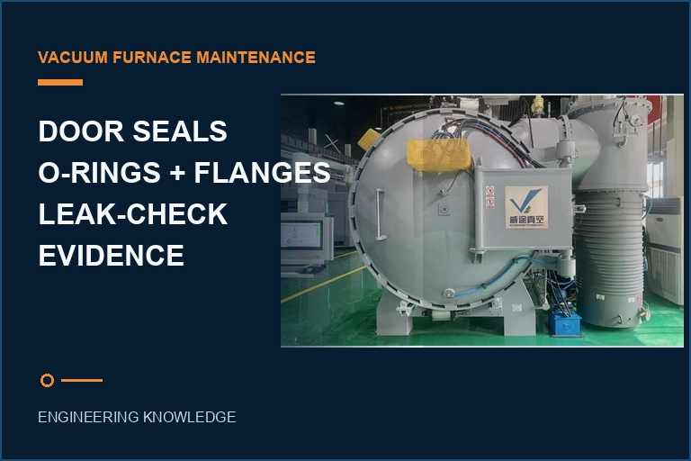
Vacuum furnace door seal maintenance should preserve the complete sealing interface: the approved O-ring material and size, a clean undamaged groove, smooth mating faces, controlled lubrication only when specified, even door alignment and the qualified closing force. Inspect and document the seal before replacement, confirm the repair with the furnace cold and in its defined test state, and distinguish a true leak from outgassing, trapped contamination, elastomer permeation or an unrelated vacuum-system fault. Replacing the O-ring alone is not proof that the door seal is restored.
Define the seal symptom and furnace state before opening the door
Start with the observed condition. Record whether the problem is slow pump-down, a high base pressure, an unacceptable rate-of-rise result, a local tracer response, visible seal damage, residue on the flange, unstable performance after heating or a change that appeared after door work. Note when it occurs: cold and empty, loaded, during heat-up, at temperature, during cooling or only after the chamber has been open. A symptom tied to one furnace state gives maintenance a testable question; the statement “the door leaks” does not.
Capture the vacuum-system configuration. Identify the chamber, door, pumping path, valve states, gauges, test connection, hot-zone condition, recent load, process gas, elapsed pumping time and recent maintenance. A door-seal diagnosis can be confused by an open bypass, dirty gauge, valve-seat problem, pump condition, moisture, hot-zone desorption or a load that releases gas. Preserve the original pressure trend and alarms before changing parts so the repair can be compared with a genuine baseline.
Make the equipment safe under the approved lockout, cooling and stored-energy procedures before inspecting the door. A large furnace door and its closing mechanism can move unexpectedly or retain mechanical energy. Hot surfaces, contaminated seals and cleaning chemicals create additional hazards. Never defeat an interlock, reach into a moving closure or use an improvised tracer around an unsafe hot furnace to accelerate diagnosis.
Define what will count as restoration. The acceptance state should name the furnace temperature, load condition, valve and pumping configuration, stabilization time, gauge or leak detector, test method, acceptance limit, responsible reviewer and records retained. If the door was tested cold and empty, do not describe that result as proof of the hot loaded cycle unless the governing procedure establishes that relationship.
Understand the O-ring, groove, flange and closing interface
An elastomer door seal works as a designed interface, not as a loose gasket pressed harder until the leak disappears. The approved O-ring cross-section, material and groove geometry establish how the seal is retained and compressed when the mating faces close. Alignment, face contact and the closing mechanism determine whether compression is distributed around the circumference. NIST notes that elastomer vacuum flanges depend on a defined O-ring and groove relationship, while excessive compression or damaged mating surfaces can create a faulty seal.
Inspect the complete circumference conceptually. A short region with contamination, a scratch that bridges the sealing path, a rolled O-ring, a twisted section, a local groove defect or uneven door alignment can create a leak even when most of the seal looks healthy. Conversely, a visibly flattened seal does not establish the leak rate by itself. Record location references around the door so findings, repairs and tracer responses can be compared at the same physical position.
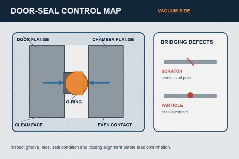
Avoid treating extra grease or extra closing force as universal repairs. NIST vacuum guidance warns that over-tightening can exceed the intended compression and that grease can interfere with proper closure or migrate into sensitive vacuum equipment. Some furnace designs and approved elastomers may use a specified lubricant, but the exact product, amount and application must come from the furnace and seal instructions. An improvised compound can swell the elastomer, trap particles, contaminate the chamber or hide a damaged surface without restoring the designed interface.
Consider temperature and chemical exposure. Elastomer selection depends on operating temperature, cooling history, process gases, cleaning agents, oils and other contact media. Compression set, hardening, swelling, cracking and loss of elasticity can develop differently across materials and service histories. Do not substitute an O-ring based only on color or nominal diameter. Record the approved material, part number or specification, cross-section, lot where required and installation date.
Inspect, clean and install without creating a new leak path
Photograph and record the seal before removal when the condition is safe to inspect. Mark the orientation and the physical location of cuts, flat regions, adhesion, particles, deposits, shiny rub marks or extrusion. Inspect the groove and mating flange for embedded debris, burrs, corrosion, impact, coating loss, scratches and deposits. A mark that crosses the shortest sealing path deserves particular attention, but its acceptance or repair method must follow the equipment specification rather than an improvised polishing decision.
Use only the approved cleaning method and materials. Prevent lint, abrasive residue, sharp tools and incompatible solvent from entering the groove or chamber. Do not scrape a precision face with a harder unapproved tool or round over a groove edge to remove one defect. If a surface requires dressing, machining or coating repair, control the work as a dimensional maintenance operation and verify the resulting geometry before installing the seal.
Confirm the replacement identity before opening its package at the work area. Check material, size, cross-section, specification or part number, storage condition and shelf-life controls where applicable. Inspect for cuts, twists, contamination and packaging damage. Install without stretching, rolling or pinching the ring beyond the approved method. For a large circumference, use location marks and a second check so a locally twisted section is not hidden when the door closes.
| Inspection surface | Evidence to retain | Decision protected |
|---|---|---|
| Removed O-ring | Material identity, orientation, damage map, compression condition and exposure history | Replace a failed seal without discarding the cause evidence |
| Groove and flange faces | Cleanliness, scratches, burrs, deposits, dimensions and approved repair record | Prevent a bridging path or geometry defect from surviving the replacement |
| Closing mechanism | Alignment, hinge or guide condition, stops, closure indication and interlock function | Confirm even repeatable contact around the circumference |
| Post-maintenance test | Defined furnace state, method, instrument, stabilization, result and local checks | Demonstrate restoration rather than assuming it from new parts |
Close the door through the approved mechanism and observe alignment, stops, indications and interlocks. Do not use increased force to pull a misaligned door into position. Compare hinge, guide, latch or actuator condition with the equipment instructions and prior known-good state. If closure is uneven, stop and correct the mechanism or geometry before vacuum testing; a new O-ring should not be used as a flexible shim for a door problem.
Separate a real leak from outgassing, permeation and other gas loads
Reassemble and pump the furnace in a defined state before diagnosing the result. A new seal, freshly cleaned groove, open chamber or changed hot zone can release gas that alters early pump-down. Moisture, cleaning residue and the elastomer itself can contribute a time-dependent gas load. NASA's leakage-testing guidance also notes that elastomers can become permeated by helium, which matters when interpreting a tracer response over time. Record the test sequence and avoid repeating tracer exposure until a rising background can no longer be distinguished from a new leak.
Use total-pressure behavior and local leak evidence for different questions. Rate-of-rise can describe the combined gas load under its defined isolation state, but it does not locate the source. A tracer method can support localization when the detector, background, dwell, application order and component state are controlled. Residual gas analysis can show a coordinated air-like or moisture-dominated pattern, but it does not prove that the door is the path. Select the next test from the evidence rather than assigning every high pressure to the largest seal.
Check simple configuration causes before repeating a long test. Confirm valve state, gauge range, pump connection, vent valve, service ports, thermocouple feedthroughs, viewports, shaft seals and recent maintenance boundaries. If the door response changes with gentle approved local tracer application, record the exact circumferential location and time. Do not flood the full perimeter and then claim one point was found; the application sequence and detector response time determine whether localization is defensible.
Preserve both passing and failing records. A repair that improves pump-down but does not meet the defined acceptance still requires investigation. A result that passes once after repeated door cycling may indicate an alignment or seating sensitivity that deserves maintenance review. Compare the same furnace state, elapsed time and instrument conditions with the known-good baseline. If the baseline method has changed, establish a bridge comparison before using the old limit.
Control changes and preventive door-seal work
Turn the repair into a maintainable baseline. Record the installed seal identity, groove and face condition, cleaning method, lubricant when explicitly approved, door alignment findings, closure checks, cold vacuum result, local leak-test result when required, work order, personnel and date. Link the record to the furnace and door rather than relying on a general spare-parts log. The next investigation should be able to compare both service life and failure location.
Set inspection frequency from risk and observed service, not from an invented universal replacement interval. Door-opening cycles, process temperature, cooling exposure, contamination, cleaning chemistry, material compatibility, mechanical alignment and storage all affect the seal. Routine checks may include visible cleanliness, closure behavior, pressure trend and defined leak evidence. Replacement frequency should follow the equipment, seal supplier, applicable procedure and the furnace's demonstrated history.
Define change triggers. Engineering review or requalification may be required for a different elastomer, size, groove repair, flange machining, coating change, lubricant, cleaning agent, closing-force adjustment, hinge or guide work, actuator change, hot-zone or process-gas change, higher operating temperature, new contaminant route or unexplained leak recurrence. A dimensionally similar seal is not automatically equivalent when material behavior, permeation, chemical exposure or temperature capability changes.
Keep the spare and storage system controlled. Protect O-rings from heat, light, ozone, deformation, contamination and mixed identification according to supplier guidance. Store parts so technicians can verify the approved identity before installation. Retain clean packaging until the seal reaches the controlled work area. A technically correct maintenance procedure can still fail when the spare is aged, misidentified or contaminated before the furnace door is opened.
Match furnace design and service access to the seal plan
SYNHTE's Vacuum Heat Treatment Furnace range includes the Vacuum Annealing Furnace, whose chamber door, vacuum package, controls, hot-zone selection and cooling route are configured around the load and process. Door-seal material, flange and groove design, closure mechanism, maintenance clearance and vacuum-test method should be reviewed with the required temperature, cleanliness, production cycles and site maintenance practices.
Share the process temperature and atmosphere, material and load, cleanliness requirement, chamber opening frequency, door orientation, available maintenance access, planned cleaning agents, site environmental conditions, required vacuum and pressure-rise test state, leak-detection method, spare-parts policy, production schedule and documentation needs. Ask how the proposed door alignment, seal access, closure indication, interlocks, pumping connections and service clearances support repeatable maintenance. When the process route is still uncertain, a controlled heat-treatment process discussion can help define the equipment and acceptance brief.
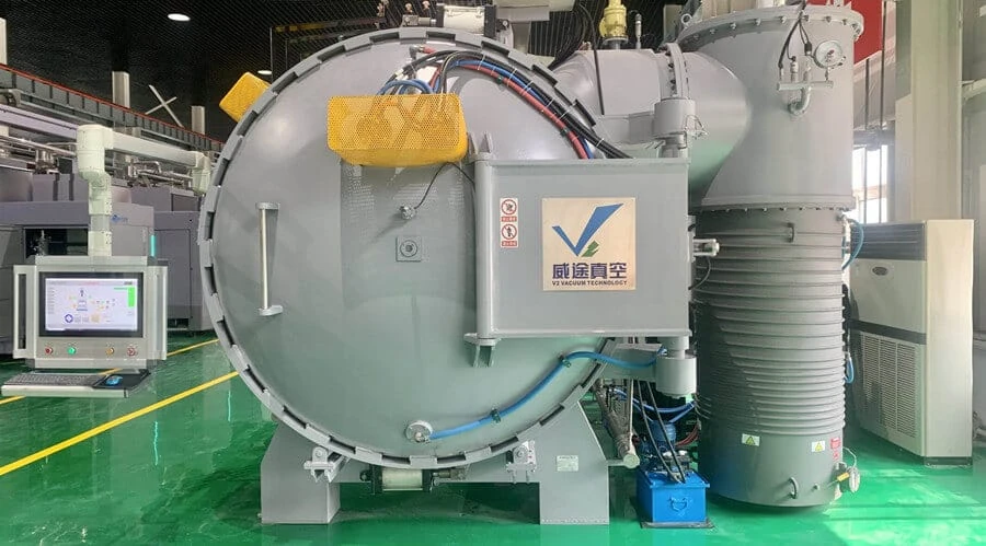
Vacuum Annealing Furnace
SYNHTE vacuum annealing furnaces combine a vacuum chamber, large service door, hot zone, pumping package, controls and cooling interfaces. Door-seal material, groove and flange condition, closing alignment, maintenance access and the agreed vacuum-test method should be reviewed with the selected temperature, cleanliness and production requirements.
What to include in your enquiry
- Exact material, incoming condition and governing drawing or specification
- Part, interface, fixture, stack and production-load drawings
- Required process outcome, acceptance methods, limits and sample locations
- Current process route, fixed variables, development questions and known risks
- Batch volume, data-retention needs, utilities, site interfaces and delivery requirements