Continuous Vacuum Brazing Changeover: Carriers, Recipes and First-Off Qualification
A continuous vacuum brazing changeover is complete only when the new product family is connected to the correct carrier, fixture, filler route, recipe, atmosphere boundary, traceability record and first-off acceptance plan. Control the last-good and first-good boundaries, verify physical and digital setup independently, demonstrate thermal and vacuum or gas recovery under a representative load, and release normal production only after the agreed joint, dimensional and process evidence passes.
Define the last-good and first-good production boundary
Start by defining what changes between the outgoing and incoming product families. Record base alloys, filler grade and form, binder or flux restrictions, joint geometry, part mass, carrier loading, fixture, cleaning route, allowable exposure before furnace entry, recipe, vacuum or protective-gas limits, cooling route and acceptance tests. A change in only the part number can still create a new thermal mass, outgassing load or joint-quality risk. Conversely, two drawings may remain inside one qualified family when their controlled inputs and acceptance evidence are demonstrably bounded by the same route.
Mark the production boundary with traceable parts and records. Identify the last accepted assembly from the outgoing family, the last carrier that entered the line, the time and recipe revision, any remaining work in buffers, and the first carrier assigned to the incoming family. This boundary prevents mixed material, mixed filler, stale recipe selection or an unverified carrier from being hidden inside a continuous flow. It also defines which product is affected if the line later reveals an abnormal atmosphere, temperature or tracking event.
Decide which changeover activities can occur externally while the current family still runs and which require the line to stop or enter an approved idle state. External work may include staging cleaned fixtures, verified filler, controlled documents and inspection tools. Internal work may include removing product-specific carriers, cleaning accessible contact surfaces, changing recipe permissions or confirming isolation and purge conditions. The applicable safety procedure, lockout requirements and equipment instructions govern access; production pressure must never convert a maintenance or isolation activity into an informal shortcut.
Measure changeover from the last good part of one family to the first good part of the next, not merely from conveyor stop to restart. NIST describes quick changeover in that last-good to first-good form, which is useful because it keeps inspection and process recovery inside the production definition. The objective is controlled restoration of saleable output, not the fastest possible motion of an empty line.
Freeze carrier, fixture, datum and contamination controls
Treat the handling system as part of the brazing process. Assign carrier and fixture identities, drawing revisions, permitted product families, load limits, maintenance status and inspection points. Define the locating datums, orientation features, supports, stops and filler-access clearances that make the assembly repeatable. A fixture that fits the conveyor can still be wrong for the joint if it changes restraint, blocks heating, collects residue or allows the part to move during transfer.
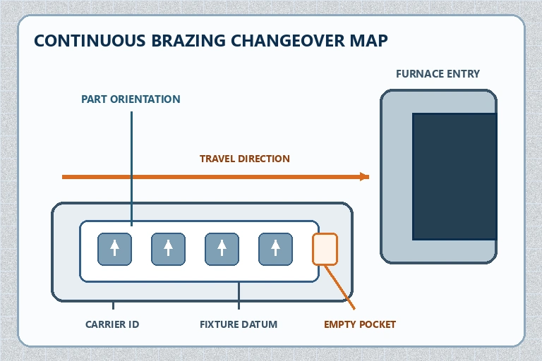
Use a setup map that an operator and quality reviewer can interpret independently. Show the carrier travel direction, fixture datum, part orientation, reference corner, allowed pockets, intentionally empty positions and identity location. Record part count, spacing, fixture mass and any risk-based center or edge position used for thermal or product evidence. Avoid relying on memory, a photograph without labels or a recipe name that does not prove the physical setup.
Control cleanliness at the changeover boundary. Remove outgoing filler fragments, masking or stop-off residue, binder deposits, damaged supports and foreign material according to the approved method. Stage incoming parts and fixtures under their defined cleaning and storage controls. Do not assume that an empty-looking carrier is chemically clean or that a general wipe removes process-specific residue. Where a shared carrier is permitted, qualification should define the cleaning method and the evidence that prevents cross-contamination between families.
Check wear and dimensional condition before release. Inspect contact faces, locating features, fasteners, conveyor interfaces and any area exposed to repeated heating. Define repair and retirement criteria through the tooling procedure rather than correcting a worn datum with an unrecorded shim. If several fixtures are interchangeable, preserve each identity and demonstrate that they remain inside the same dimensional and thermal envelope.
Verify recipe, identity and line permissions independently
Recipe selection must be linked to the incoming product family but verified separately from the physical carrier. Record the approved recipe identifier and revision, permitted material and filler route, carrier or part identifier, user access level and effective date. Require a controlled comparison between the work order, carrier identity and selected recipe before the first incoming carrier is released. A barcode or manufacturing execution system link can reduce manual entry, but the project must still define how mismatches, unreadable codes, duplicated identifiers and network loss are handled.
Review every parameter that can change the process boundary: conveyor speed or index timing, zone setpoints, equalization and brazing windows, vacuum or gas sequence, cooling settings, alarm limits, interlocks, data tags and downstream handshakes. Protect engineering limits from routine operator changes and preserve an audit trail for authorized revisions. Do not copy an old recipe under a new name without confirming that hidden settings, units, timers and permissions are correct.
Test the decision chain, not only the display. Confirm that an incoming carrier calls or permits the intended recipe, that the programmable logic controller uses the expected units and tags, and that a deliberate mismatch produces the defined hold or alarm. Verify line-stop and recovery logic for a carrier fault, vacuum or gas deviation, sensor failure and downstream blockage as required by the project protocol. The test method must be safe and agreed; it should not introduce a condition outside the equipment design.
Preserve a digital thread that connects drawing and fixture revision, material and filler lot, cleaning status, carrier identity, recipe revision, time stamps, process records and inspection results. NIST manufacturing-data guidance emphasizes traceability and trustworthiness across manufacturing information. The useful application here is practical: a reviewer should be able to reconstruct which physical and digital state produced the first accepted assembly after changeover.
Demonstrate thermal and atmosphere recovery under load
An empty restart does not prove that the incoming product family has recovered its qualified brazing environment. The new load can change thermal residence, outgassing, gas consumption, pressure response and cooling behavior. Define a representative first carrier or controlled verification load that reflects the incoming fixture mass, part count, surface preparation, filler route and orientation. Use the approved thermal and pressure evidence rather than assuming that normal screen values mean the joints experienced the qualified condition.
Review zone temperatures, relevant load or process thermocouples when required, conveyor timing, pressure or gas-quality records, isolation response, alarms and cooling. For a vacuum route, preserve pump-down or process-pressure behavior at the critical stage and investigate abnormal outgassing or recovery before continuing. For a protective-gas route, use the specified gas identity, purity, dew point or oxygen limit, purge sequence and monitoring method. The live SYNHTE continuous furnace page explicitly treats vacuum and gas architectures as application-dependent options, so neither route should be inferred from the product name alone.
| Release gate | Evidence to retain | Question answered |
|---|---|---|
| Physical setup | Carrier, fixture, datum, orientation, count and cleanliness | Is the incoming assembly loaded in the approved state? |
| Digital setup | Work order, recipe revision, permissions, identity match and audit trail | Will the line execute and record the intended route? |
| Process recovery | Thermal, vacuum or gas, conveyor, alarm and cooling records | Did the representative carrier receive the qualified exposure? |
| First-off acceptance | Joint, leak, dimensional, visual or other agreed results by position | Has the new family returned to saleable output? |
Define response limits before the first carrier enters. If recovery takes longer than expected, protect every affected carrier and investigate the physical and digital setup, contamination load, isolation state, sensor evidence and equipment condition. Do not shorten residence time, increase temperature or bypass an alarm merely to restore takt. A controlled confirmation may justify resuming production; an unexplained deviation should remain visible in the change record.
Release the first-off assembly before ramping back to rate
Define first-off acceptance from the drawing, brazing procedure and quality plan. Depending on the assembly, the evidence may include filler-flow or fillet observations, leak testing, dimensional checks, mechanical testing, metallography, cleanliness, surface condition and process-record review. Not every method applies to every joint. State the method, sample or inspection position, limit, responsibility and disposition before changeover so production urgency does not decide the test after the part exits.
Preserve position and carrier identity. An assembly from an easy edge pocket cannot automatically represent a shielded center position, a different fixture or a later carrier after the line has reached steady state. Where the first carrier is intentionally conservative or lightly loaded, define how the subsequent ramp demonstrates the normal production envelope. Conversely, do not release a full-rate sequence behind an unreviewed first-off part if inspection time is longer than the line buffer can safely contain.
Separate first-off acceptance from statistical process control. One accepted assembly verifies the defined startup state; it does not prove long-term stability or capability. ISO 11462-1:2026 provides current guidance on statistical process management and explicitly frames process stability and performance as ongoing work. Apply only the standards and methods agreed for the project, and build control charts or capability studies from comparable data rather than mixing product families, fixture revisions or changing inspection methods.
Close the changeover record with actual duration, stopped time, first-good time, rejected or held carriers, deviations, corrective actions and lessons that can be standardized safely. Trend recurring causes such as missing staged tools, worn datums, slow atmosphere recovery, recipe mismatch or delayed inspection. Improvement should remove waste while keeping every safety, process and acceptance gate explicit.
Match line architecture to the changeover policy
SYNHTE's Vacuum Brazing Furnace Systems include a Continuous Vacuum Brazing Furnace configured around stable product families, carrier loading, thermal residence, vacuum or protective-gas boundaries, controls and line interfaces. The current product page makes changeover policy an engineering input rather than an implied catalogue feature. That distinction protects the project from buying continuous capacity for a product mix that cannot be changed over predictably.
Share the product-family matrix, drawings, materials, filler routes, cleaning methods, carrier and fixture concepts, good-part target, validated thermal window, vacuum or gas requirements, changeover frequency, first-off tests, buffer capacity, traceability fields, upstream and downstream handshakes, utilities and site safety interfaces. Ask how isolation stages, zone layout, conveying, recipe control, service access and recovery logic support the agreed changeover boundary. If the joining route or acceptance method is still being developed, a controlled brazing process service discussion can help define representative trials before the production line is fixed.
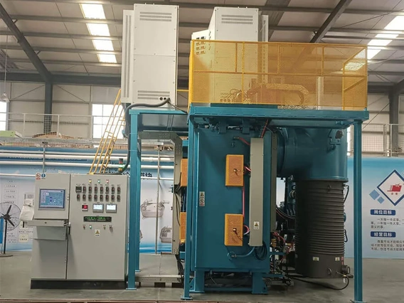
Continuous Vacuum Brazing Furnace
SYNHTE continuous vacuum brazing lines are configured around stable product families, carrier loading, validated thermal residence, vacuum or protective-gas boundaries, automation, traceability and acceptance evidence. A useful project review defines the changeover policy and first-good-part boundary before line rate is treated as an equipment output.
What to include in your enquiry
- Exact material, incoming condition and governing drawing or specification
- Part, interface, fixture, stack and production-load drawings
- Required process outcome, acceptance methods, limits and sample locations
- Current process route, fixed variables, development questions and known risks
- Batch volume, data-retention needs, utilities, site interfaces and delivery requirements