
Vacuum Furnace Hot-Zone Condition Monitoring: Power Drift, Uniformity and Replacement Evidence
Vacuum furnace hot-zone condition monitoring should combine a documented healthy baseline with power demand, heating response, zone balance, temperature evidence, vacuum behavior, visual inspection and maintenance history. No single trend proves that the hot zone has failed. Diagnose changes against the same load and recipe where possible, separate sensor and utility causes, inspect physical condition, and define which repairs require conditioning, temperature verification or wider requalification before production resumes.
Establish a healthy baseline before looking for degradation
Condition monitoring begins when the furnace is known to be operating acceptably, not after a failure. Record hot-zone identity, material and configuration, heating-element or band arrangement, insulation or shield construction, control-zone mapping, sensor identities, recent maintenance, vacuum-system state and the qualified usable work zone. Link this equipment baseline to the recipe, representative load and temperature evidence used to declare the condition acceptable.
Choose repeatable indicators. Useful records may include time to reach defined recipe points, power output by zone, controller demand, zone-to-zone balance, overshoot or recovery behavior, vacuum pressure during comparable thermal phases, pressure-rise or leak evidence under a defined method, cooling response and production-load results. Record utilities and load mass because supply voltage, cooling-water condition, gas pressure and thermal mass can change the same trends that operators may attribute to the hot zone.
Define comparison windows rather than one perfect number. Production data naturally varies with load, starting temperature, fixture, recipe and maintenance state. Group like-for-like runs and retain enough context to explain the variation. A trend based on different materials, load masses and peak temperatures can create a false alarm or hide a real zone-specific change. Use a controlled empty or reference cycle only when its purpose, configuration and acceptance basis are documented.
Set review ownership and frequency. Operators can flag abnormal sounds, visible damage, slow heating and zone imbalance; maintenance can inspect electrical and mechanical condition; process engineering can compare cycle and uniformity evidence; quality can decide whether production remains inside the approved state. The monitoring plan should state who receives an alarm, which records are protected and when a deviation requires containment rather than an informal adjustment.
Read power, temperature, vacuum and physical evidence together
Power demand can reveal a change, but it is not a diagnosis by itself. Higher demand in one zone may be associated with a damaged element, loose connection, insulation loss, changed sensor response, altered load placement or different heat loss at the door or feedthrough. Lower demand can result from a control or measurement problem as well as a thermal change. Compare electrical indicators with heating rate, temperature response, load condition and maintenance history before opening the furnace or changing a recipe.
Temperature evidence has several roles. Routine control and load records show how the process responded during production. System accuracy tests, temperature uniformity surveys and other pyrometric checks answer defined questions under their governing procedure. A favorable survey does not make every later production load acceptable indefinitely, while one slow production cycle does not automatically invalidate the qualified work zone. Use each record within its stated method and time boundary.
Vacuum behavior can expose hot-zone contamination, absorbed moisture, deposited process residue, damaged insulation or a separate leak and pumping problem. Review pressure against the same thermal phase because outgassing changes as the furnace heats. Compare chamber cleaning, vent history, fixture condition and recent material loads. A rising hot pressure with normal cold leak evidence suggests a different investigation path from a cold pressure-rise failure.
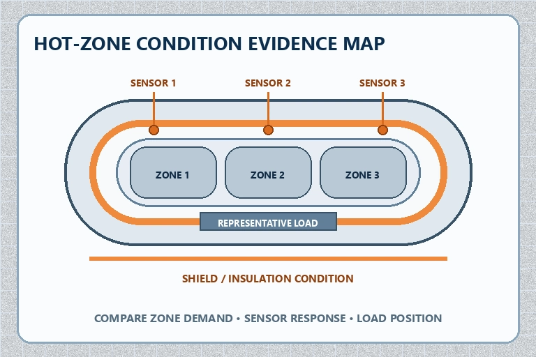
Physical evidence completes the picture. Inspect elements, connectors, supports, insulation layers, shields, feedthroughs, sensor routing and contamination patterns using the approved safe-access procedure. Record location and extent with a consistent zone map. A photograph without location identity is difficult to trend; a zone tag connected to power and temperature records can show whether repeated discoloration, distortion or deposits align with a measurable process change.
Separate hot-zone causes from sensors, utilities, loads and vacuum faults
Use a cause matrix before replacing parts. A longer heat-up with similar zone power may point toward a heavier load, lower starting temperature or changed recipe. Higher power with similar load and slower response may increase suspicion of heat loss, element condition or supply issues. A single zone deviation may suggest a local element, connection, sensor, controller or insulation problem. A chamber-wide change should prompt review of utilities, recipe, load and common measurement paths as well as the hot zone.
| Observed change | Compare first | Do not conclude yet |
|---|---|---|
| One zone needs more power | Sensor response, electrical connections, element continuity, local insulation and load position | That the complete hot zone requires replacement |
| All zones heat more slowly | Load mass, starting condition, supply voltage, recipe revision and common heat loss | That every heating element has degraded equally |
| Hot pressure is worse | Recent loads, cleaning, venting, fixtures, deposits and cold leak evidence | That the chamber has a structural leak |
| Temperature evidence shifts by position | Sensor identity, routing, load map, fixture and zone-control history | That a recipe offset is the correct repair |
| Visible shield or insulation damage | Location, extent, loose material risk, power trend and approved service criteria | That production may continue without engineering review |
Verify the measurement chain before compensating the process. Confirm sensor identity, calibration or verification status, installation depth, polarity, routing, connectors, instrument channel, correction factors and software configuration as applicable to the approved system. A drifted or moved sensor can make a healthy zone appear weak. Raising the recipe or applying an undocumented offset can then create a real overheating risk while concealing the original measurement problem.
Check utilities under load, not only at idle. Supply voltage, phase condition, transformer or power-controller behavior, cooling-water temperature and flow, gas supply and exhaust condition can affect heat-up, stability and equipment protection. Retain electrical work and utility deviations with the furnace history. A temporary plant event should not be written into the long-term hot-zone baseline as if it were material degradation.
Preserve production evidence when the cause is uncertain. Quarantine affected loads according to the quality plan, retain original trends and avoid changing several variables at once. A controlled diagnostic cycle can compare one repaired or verified surface at a time. This method takes longer than adjusting the recipe immediately, but it protects the evidence needed to distinguish a component defect from a load, sensor or utility change.
Inspect and document the hot zone with a repeatable zone map
Plan inspection around the equipment manufacturer's procedure, stored-energy controls, cooling state, contamination risk and site safety requirements. Never enter or touch a chamber because it appears cool from outside. Isolate electrical, hydraulic, pneumatic and gas energy as applicable, verify the safe condition and protect fragile insulation or shields from unnecessary contact. The monitoring article does not replace the machine-specific service manual or local lockout procedure.
Use consistent location names. Divide the hot zone by control zone and by physical references such as door side, rear, top, bottom, left, right, center and feedthrough position. Record heating elements or bands, connectors, support hardware, insulation or shield layers, fasteners, sensor entry points and work supports. Photograph the same reference views when practical and add a scale only when it can be placed safely without contaminating or damaging the assembly.
Look for change rather than a universal appearance. Relevant observations may include broken or distorted elements, loose connections, arcing evidence, cracked supports, displaced insulation, shield distortion, gaps, fastener loss, deposits, flaking, contamination trails or damage near a feedthrough. The acceptable response depends on hot-zone material, equipment design, process cleanliness and the manufacturer's criteria. Do not publish one color, crack length or power percentage as a universal replacement limit.
Link every repair to the zone map and removed component identity. Record why the work was opened, what was found, parts replaced, cleaning method, torque or connection verification where applicable, sensor disturbance, insulation or shield work, electrical checks, leak checks and who released the mechanical work. This history helps engineering distinguish gradual wear from an event and supports later review when the same location begins to drift again.
Define conditioning, return-to-service and requalification after repair
Not every repair has the same process impact. Replacing an external display component differs from changing a control sensor, heating element, major connection, insulation section, radiation shield, feedthrough or hot-zone assembly. Classify work by its potential effect on temperature measurement, zone control, heat loss, vacuum cleanliness, usable work zone and load results. Use that classification to select the required checks rather than automatically repeating every qualification or doing none.
After work inside the chamber, define cleaning and conditioning requirements. New or disturbed materials, handled insulation, cleaning residues and opened vacuum surfaces can affect pressure during heating. A controlled bakeout or empty conditioning cycle may be required by the equipment procedure. Record pressure behavior, heating response and any hold or acceptance condition. Do not load customer parts merely to accelerate conditioning unless that use and resulting disposition are approved.
Verify the surfaces affected by the repair. This may include electrical continuity and insulation checks, sensor verification, control-zone response, cold leak or pressure-rise testing, hot vacuum behavior, alarm and interlock checks, system accuracy or temperature uniformity work, a reference cycle and representative product evidence. Follow the applicable customer, regulatory and pyrometry requirements. The scope should be justified from the repair, not selected only because a convenient test passed.
Update the baseline after acceptance. Preserve pre-repair trends, repair evidence, test results and the new healthy condition. Do not overwrite the old baseline or make the repaired system look as though it never changed. The comparison point should identify hot-zone revision, sensor configuration, recipe and load so future analysts know which records are legitimately comparable.
Match furnace configuration and records to the monitoring plan
SYNHTE's Vacuum Heat Treatment Furnace Systems include the Vacuum Annealing Furnace for controlled heating, vacuum processing and cooling of defined production loads. Equipment review should address hot-zone material, control-zone arrangement, usable work zone, sensor and record functions, vacuum system, cooling route, maintenance access and the acceptance evidence required by the application.
Share the material, process temperatures, cleanliness requirement, largest fixture and load, production recipes, governing pyrometry or customer requirements, data-retention needs and maintenance strategy. Ask how the proposed control system exposes zone demand, sensor status, alarms, recipe revision and batch records. If the process window or monitoring baseline still needs representative trials, a controlled heat-treatment service discussion can help define evidence before equipment configuration is finalized.
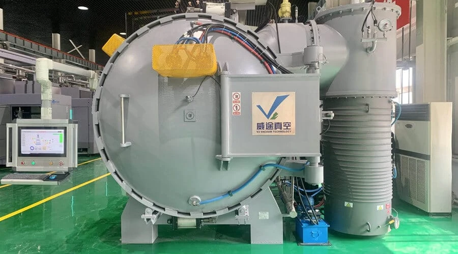
Define factory and site acceptance boundaries clearly. Equipment tests can verify agreed control, vacuum, alarm, interlock and thermal functions under stated conditions. Production process qualification connects those functions to representative loads and acceptance results. A hot-zone monitoring plan should identify which evidence belongs to routine operations, preventive maintenance, pyrometry compliance, process qualification and equipment service so the organization does not mistake one passing record for proof of every other surface.
Use condition trends without hiding process risk
Trend tools should help people ask better questions, not automate acceptance beyond the approved plan. Display like-for-like cycles, zone values and maintenance events together. Mark recipe changes, sensor work, hot-zone repairs, major cleaning, load-family changes and utility deviations on the timeline. A smooth average can hide a repeating edge-position issue, while a single outlier may come from a documented plant event. Retain the underlying record and location identity.
Set alert, action and stop conditions with different meanings. An alert may prompt review while production remains inside the approved window. An action condition may require maintenance or increased verification at a planned point. A stop or containment condition protects equipment, personnel or product and should not be bypassed by changing a dashboard threshold. Align condition monitoring with the existing alarm, interlock, quality and change-control system.
Review the plan after confirmed findings. When an element, connection, shield, insulation section, sensor or external utility is proven to be the cause, update the diagnostic matrix so the evidence chain becomes faster and more accurate. Also record false alarms and why they occurred. This learning prevents repeated unnecessary hot-zone replacement and helps the organization recognize smaller, zone-specific changes before they become broad process disruptions.
The final decision is evidence based: continue under the approved state, plan maintenance, contain affected production, perform a defined repair, or requalify the affected surfaces. Keep the reasoning with the furnace history. A replacement decision that can be explained from power, temperature, vacuum, inspection and production evidence is more defensible than one based on appearance or age alone.
Vacuum Annealing Furnace
A vacuum heat-treatment system should provide stable zone control, usable process records, maintainable heating and insulation components, and defined access for inspection and service. The applicable hot-zone material, sensor arrangement, vacuum system, cooling route and acceptance evidence are configured around the workpiece, process temperature, cleanliness requirement and production load.
What to include in your enquiry
- Exact material, incoming condition and governing drawing or specification
- Part, interface, fixture, stack and production-load drawings
- Required process outcome, acceptance methods, limits and sample locations
- Current process route, fixed variables, development questions and known risks
- Batch volume, data-retention needs, utilities, site interfaces and delivery requirements