
Vacuum Tempering Cycle Qualification After Hardening
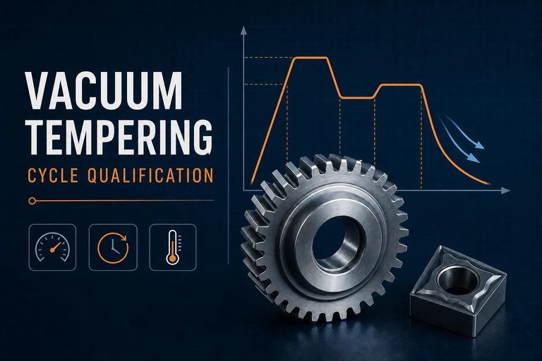
A vacuum tempering cycle qualification should prove that the complete production load reaches the intended thermal condition and delivers the required hardness, toughness, dimensional stability, and surface state. A controller recipe alone is not qualification evidence. Engineers need a documented relationship among the hardened condition, load arrangement, heating and soak behavior, atmosphere, cooling route, and measured part results. This article provides a practical framework without prescribing material-specific temperatures or acceptance limits that belong in the drawing, material specification, or approved heat-treatment procedure.
Define acceptance before choosing the tempering recipe
Tempering begins with the hardened part and an engineering requirement, not with an empty furnace program. Record the steel grade and condition, hardening route, elapsed time before tempering, section thickness, critical dimensions, target hardness range, required toughness evidence, and surface-finish constraints. Where a drawing or customer specification controls the work, that document remains the authority. The qualification plan should translate each requirement into a measurement, sampling location, responsible person, and disposition rule.
Hardness should be treated as a distribution across representative parts and locations rather than a single convenient reading. Dimensional checks should focus on features that can move during heating or cooling. Surface acceptance may include visible oxidation, discoloration, contamination, or residue, but appearance must not be used as a substitute for metallurgical evidence. If multiple tempering cycles are required, each cycle and the allowed delay between cycles should be documented.
| Question | Evidence | Why it matters |
|---|---|---|
| Did every load region see the intended cycle? | Qualified survey or load thermocouple records | Controller temperature does not prove part temperature. |
| Did properties land in range? | Hardness and specified mechanical tests | Thermal history must produce an acceptable result. |
| Did geometry remain acceptable? | Before-and-after checks on critical dimensions | Stress relief can reveal or redistribute distortion. |
| Was the surface protected? | Visual criteria and, where required, cleanliness checks | A bright cycle must control reactive exposure. |
Qualify the production load, not an idealized test load
Part temperature depends on mass, section thickness, spacing, fixture contact, radiation view factors, and any gas-assisted convection used at lower temperature. A light development load may heat much faster than a dense production basket. Qualification therefore needs a representative worst-case arrangement: the heaviest approved load, the most shielded part positions, and the fixture geometry expected in production. Avoid changing basket density, part orientation, or fixture material without evaluating whether the change remains inside the qualified envelope.
Place load sensors where the thermal lag is expected to be greatest, while protecting the measurement method from movement or false contact. Compare those readings with the control sensor and the qualified furnace working zone. The soak period should begin from the defined process condition, not simply when the controller first reaches setpoint. For some procedures that means waiting until the slowest monitored part location reaches an agreed threshold. Record the rule explicitly so operators do not apply different interpretations.
Control atmosphere and cooling as part of the same cycle
Vacuum level, backfill gas, convection mode, and cooling practice can affect surface condition and thermal uniformity. The correct route depends on the material, prior hardening process, surface requirement, and furnace design. A clean vacuum or controlled protective atmosphere can limit oxidation and discoloration, but it cannot correct oil, detergent, machining-fluid, or handling contamination already present on the load. Incoming cleanliness and dry fixtures are therefore part of the process boundary.
The live vacuum heat-treatment furnace range provides the broader equipment context, while the Vacuum Tempering Furnace page describes a platform intended for bright tempering, stress relief, controlled atmosphere processing, and optional convection. Those equipment capabilities still need to be matched to the approved material procedure. During cooling, define the gas, pressure or circulation state, unload temperature, and any restriction intended to prevent oxidation, thermal shock, or handling damage. Do not assume that faster cooling is always better; the required outcome and distortion risk govern the choice.
Build a repeatable production evidence package
A useful qualification package lets another trained team reproduce the cycle and recognize drift. Keep the approved recipe revision, furnace identification, working-zone qualification status, load drawing, fixture identification, sensor map, raw time-temperature record, vacuum or atmosphere record, alarm history, hardness results, dimensional results, surface observations, and nonconformance disposition together. Photographs can support load configuration records, but they do not replace measurements.
Run confirmation loads that represent normal production variation rather than repeating one carefully arranged demonstration. Review the evidence for trends: delayed heat-up in a shielded zone, increasing pressure during the hold, repeated hardness bias at one load location, or greater movement in a specific geometry. A statistically valid sampling plan depends on the governing quality system and risk; this article does not invent a universal quantity. The practical principle is to connect each critical output to a defined sample and each process input to a retrievable record.
After qualification, define change triggers. A new fixture, larger batch mass, altered part spacing, different backfill gas, sensor relocation, furnace maintenance affecting circulation, or revised material specification may require documented review and possibly partial or full requalification. This protects the meaning of the original evidence instead of treating one successful trial as permanent approval.
Equipment implications for a stable tempering process
A tempering system should be selected around the qualified load envelope and evidence needs. Discuss usable working-zone dimensions, load mass, heating method, convection option, temperature-uniformity qualification, vacuum and gas controls, cooling behavior, sensor access, recipe security, data export, and fixture handling. These questions are more useful than comparing a nominal maximum temperature in isolation.
For projects that follow vacuum hardening or oil quenching, also define how parts move into the tempering step, how delay is controlled, and how surface contamination is prevented. Share the material, hardened condition, representative load drawing, target evidence, and expected throughput with the furnace supplier so the configuration discussion is tied to the real process.
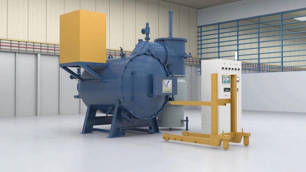
Vacuum Tempering Furnace
For post-hardening tempering, this furnace family supports clean vacuum or protective-atmosphere processing, programmable multi-step cycles, controlled cooling, and optional convection for applications that need better low-temperature load uniformity. Final configuration must be matched to the qualified load, material procedure, surface requirement, and production evidence plan.
What to include in your enquiry
- Material grade, starting condition, and controlling specification
- Part and fixture drawings, load mass, and production arrangement
- Process stages, atmosphere or vacuum requirements, and cooling route
- Acceptance tests, sampling locations, and traceability expectations
- Typical batch volume, cycle target, utilities, and site constraints
Technical references
- SAE AMS2750H — Pyrometry. This specification covers pyrometric controls for thermal-processing equipment, including sensors, instrumentation, system accuracy tests, and temperature uniformity surveys. Apply the purchased current standard together with the controlling material, customer, or process specification; it does not supply a universal tempering temperature or acceptance limit.