
Vacuum Gas Quenching Load Design: Fixtures, Spacing and Cooling Uniformity
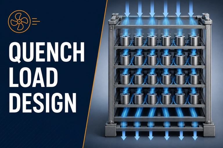
Vacuum gas quenching load design controls the available gas-flow paths around each part, the fixture restriction and the spacing between loads. A repeatable arrangement helps avoid cooling variation that is caused by the load rather than the furnace setting.
Vacuum Gas Quenching Load Design: First Checks
A gas-quench recipe is not fully defined by gas type and pressure. Parts cool according to their geometry, surface exposure, fixture contact, load density and position in the gas-flow field. Repeatable results require a qualified load pattern that gives each critical surface a predictable route for heat removal.
The gas is not the whole process
Nitrogen and argon have different process roles, but the same gas can give different part results when the load changes. Dense baskets, blocked passages, heavy fixtures and tightly nested parts reduce access to circulating gas. Thin sections may respond more quickly than thick ones; local shadowing can create a different cooling history on the same component.
Choose the gas and pressure from the alloy and required cooling response, then qualify the physical load. The existing Nitrogen vs Argon for Vacuum Gas Quenching article supports the gas decision; this guide addresses the loading decision that follows it.
Load-pattern rules that protect flow
The load view makes the desired open path for gas circulation visible; it is not a substitute for process qualification.
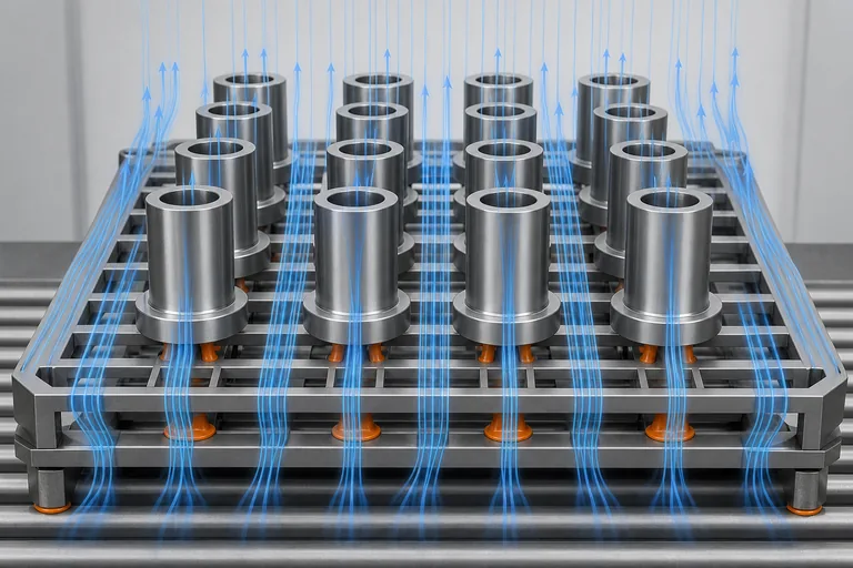
| Load feature | Desired condition | Common consequence of poor design |
|---|---|---|
| Part spacing | Consistent gaps around cooling surfaces | Local slow cooling or hardness variation |
| Fixture openness | Support with minimum obstruction to flow | Shielded regions and longer recovery time |
| Orientation | Repeatable alignment to the known flow path | Part-to-part response changes between loads |
| Mixed load mass | Keep mass and section changes within a qualified window | Thin and heavy parts cool at different effective rates |
| Basket fill level | Use documented density and stack height | Overloaded zones receive less cooling access |
Fixtures should support, not insulate
Fixtures are necessary for alignment and distortion control, but every contact surface and solid wall changes heat flow. Review contact points, material, cross-section and number of levels. A fixture that is strong enough for handling may still be too thermally heavy or restrictive for the quench target. Where distortion is critical, balance flow access with mechanical support and verify the compromise on representative parts.
Qualify the real production load
- Define part family, alloy, section range and required properties.
- Document basket, fixture, orientation, load spacing and maximum fill level.
- Set gas, pressure and quench sequence according to the approved process.
- Use representative parts or qualified monitoring to compare locations in the load.
- Record hardness, microstructure, distortion or other required acceptance evidence.
- Review any change in fixture, load density, gas, pressure or controller recipe before release.
Gas quenching can also influence distortion. Combine this loading approach with the TUS Guide and the site’s broader heat-treatment system information when setting a qualified process window.
A quench-capable furnace should be assessed against the real load, not an empty-chamber headline. Define the load envelope, fixture mass, critical surfaces, gas, pressure, flow arrangement, monitoring and acceptable cycle time before configuration is fixed.
For broader equipment selection, start with Vacuum Furnace Systems, then use the Vacuum Heat Treatment Furnace system family to compare the cycle and load-management options around this gas-quench requirement.When rapid gas cooling is part of the qualified recipe, review the Vacuum Gas Quenching Furnace so gas pressure, circulation and load design can be specified together.
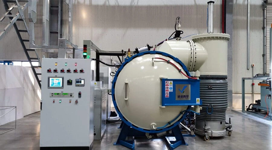
Vacuum Gas Quenching Furnace
System selection should connect the gas-quench capability with the part geometry, load design, cooling target and process records needed for production.
- Load envelope and circulation reviewed together
- Gas and pressure matched to the process
- Qualification-focused data capture
What to include in your enquiry
Provide the part and load design so cooling requirements can be assessed realistically.
- Alloy, required hardness or microstructure and critical cooling rate
- Part drawing, section range, load mass and production quantity
- Fixture/basket drawings, orientation and target fill level
- Current or required quench gas, pressure and cycle time
- Distortion limits and inspection or qualification evidence
Technical references
- SAE AMS2750 — Pyrometry — official SAE scope for control and testing of furnaces and pyrometric equipment.
- AIAG CQI-9 — Special Process: Heat Treat System Assessment — official AIAG heat-treatment system-assessment reference for controlled heat-treatment operation.