Vacuum Sintering Density Qualification: Green State, Position Mapping and Final Acceptance

Vacuum sintering density qualification should connect four controlled states: the incoming powder or green part, the mapped production load, the executed furnace cycle and the final accepted part. Density results are meaningful only when the measurement method suits the material and porosity, each sample remains tied to its physical load position, and dimensional, metallurgical or mechanical acceptance supports the same conclusion. A single center coupon or batch average cannot automatically qualify every part position, geometry or later process change.
Define the material system and the density outcome
Begin with the material and part requirement rather than a generic percentage target. Record the alloy or ceramic system, powder supplier and lot, particle or feedstock condition, binder route, forming method, green density or other incoming-state measure, section thickness, geometry, supported surfaces and governing drawing or specification. Pressed powder, metal injection molding feedstock and additively manufactured green parts can begin from very different pore structures and binder histories. A density result developed for one route should not be transferred automatically to another.
State what the final density is intended to demonstrate. The requirement may protect mechanical strength, dimensional stability, thermal or electrical performance, leak tightness, surface finishing, later heat treatment or another functional property. Define whether the drawing controls absolute density, relative density, an allowed position range, connected porosity, local microstructure or a property that only correlates with density. If a theoretical density is used for a relative value, identify its technical basis and the material condition to which it applies.
Separate process-development evidence from production release. Development may use additional coupons, sectioning or measurement methods to understand mechanisms. Production release may need a faster method or a risk-based sampling plan. Document how the release measurement was correlated to the development evidence and where that correlation stops. A convenient measurement should not be treated as equivalent merely because both values are called density.
Define the approved calculation, conditioning and reporting rules before the qualification run. Record units, significant figures, specimen preparation, temperature or moisture conditioning when relevant, instrument identity and how surface-connected porosity is handled. ASTM B962 describes Archimedes-principle methods for compacted or sintered powder-metallurgy products and explains why surface-connected porosity requires an appropriate sealing or impregnation approach. The applicable drawing, material specification and laboratory procedure still determine which method is valid for the actual part.
Control the green state, handling and load inputs
The furnace cannot correct uncontrolled variation introduced before loading. Record forming pressure or printing build identity where applicable, binder and debinding history, green mass, dimensions, visible damage, storage time, cleaning or powder-removal status and any pre-sinter treatment. Handle fragile parts with defined supports and limits. Chipping, warping, contamination or trapped powder can change local mass, shrinkage, gas evolution or contact with the setter.
Freeze the fixture and setter condition. Identify material, coating or separator, tray level, support points, contact area, orientation, spacing, load mass and part count. Setter flatness, reaction layers, residue and repair history can affect support and local chemistry. If a release agent or separator is used, control its material, thickness and placement rather than adding it informally after a sticking event.
Build a load map that preserves part identity. Assign each tray, row, carrier, fixture and selected sample a location that remains traceable through unloading and testing. Include center, edge, upper, lower, near-door or other risk-based regions only when they correspond to the actual furnace and load geometry. Do not use familiar labels without defining them on the load drawing. A later analyst must be able to reconstruct where a tested part sat and what surrounded it.
Choose the qualification load to represent production challenge conditions. Consider total mass, thermal mass distribution, part spacing, setter stack, binder or residual-gas load, thick and thin sections, and the positions expected to respond differently. A lightly loaded tray can help establish an initial route, but it does not automatically qualify a dense multi-level production stack. If several production patterns are expected, qualify the important patterns or justify the approved load envelope with evidence.
Map load positions and select representative samples
Design the sampling plan from expected variation and the consequence of missing it. Start with the physical load map, then identify positions that challenge heating, gas removal, atmosphere access, support or cooling. Center and edge locations are common labels, but the most important position may instead be a shielded lower tray, a heavy section, a part next to a large fixture mass or a geometry with restricted gas escape. The qualification rationale should explain why each selected location can reveal a meaningful difference.
Keep production parts and witnesses distinct. A separate coupon may be useful for destructive measurement or metallography, but it represents a production part only when material, green condition, section, support, gas path and thermal response are sufficiently comparable. A small loose coupon beside a large part can receive the same furnace program while experiencing a different shrinkage path and heat-transfer history. Record the limits of every witness correlation.

Select enough samples to evaluate position and normal process variation under the approved quality plan. Avoid reporting only the batch mean. Retain the individual results, position range, any excluded or damaged specimen and the reason for its disposition. When the requirement controls both minimum density and uniformity, a favorable average cannot compensate for one repeatedly weak region.
Plan destructive work before the cycle. If sectioning, microscopy or mechanical testing will consume parts, identify replacements, witness locations and traceability. Align the density plan with dimensional and metallurgical sampling so the same spatial pattern can be compared. The strongest conclusion usually comes from several evidence types tied to one part and one load position, not from unrelated samples that merely shared a batch number.
Connect the furnace cycle to part response
Retain the process record that can explain the measured result. Depending on the qualified route, this may include vacuum and pressure history, selected partial-pressure or gas-flow values, temperature channels, load thermocouples when used, heating and hold segments, debinding transitions, alarms, interventions and cooling. Distinguish programmed setpoints from measured values. A completed recipe name proves that the controller ran a sequence; it does not by itself prove what every production part experienced.
Review the cycle in relation to the load map. A pressure excursion during binder evolution, a delayed part-temperature response or a gas-control deviation may affect some materials or positions more strongly than others. Keep the event time, load position and final result connected so engineering can test a mechanism rather than changing several settings at once. Do not invent a universal vacuum, gas or temperature limit; use the approved material procedure and equipment agreement.
| Control surface | Evidence to retain | Question answered |
|---|---|---|
| Incoming and green state | Material lot, forming route, green mass/density, binder and debinding history | Did the load begin from a controlled condition? |
| Fixture and position | Setter identity, support, orientation, tray and part coordinate | Can each result be related to a physical load location? |
| Cycle execution | Pressure, gas, temperature, hold, alarm and cooling records | Did the defined production route execute without an unresolved deviation? |
| Final acceptance | Density method/result, dimensions, microstructure or required properties | Did the controlled route deliver the specified part outcome? |
Define deviation ownership before production. The team should know which alarms stop release, which excursions require engineering review, which evidence must be preserved and whether a repeat measurement, focused requalification or full rerun is justified. Automatically accepting a load because the final temperature was reached can hide a pressure, gas-flow or timing event that matters to density or chemistry.
Measure density with a method that fits the part
Density is mass divided by volume, but the practical volume method depends on the part and pore structure. Simple geometry may permit dimensional volume when surfaces and dimensions support the required uncertainty. Complex shapes or surface-connected porosity may require an Archimedes-based method with the conditioning or pore-sealing steps defined by the applicable procedure. Other materials or acceptance questions may require a different laboratory method. Choose the method from the specification and part condition, not from instrument convenience.
Establish measurement-system capability for the decision. Record balance resolution, reference standards, fluid condition where applicable, specimen preparation, repeatability, operator method and how uncertainty compares with the allowed process or product range. A result displayed to many decimal places is not automatically precise enough to distinguish a compliant part from a noncompliant one. When two laboratories or methods are used, document their correlation rather than merging the values without review.
Connect density to the properties it is meant to protect. Depending on the material and drawing, review dimensions and shrinkage, visible distortion, surface condition, microstructure, chemistry, hardness, strength, conductivity, leak behavior or another functional test. Density can be a strong process indicator, but it does not replace a required property test or reveal every local defect. Likewise, one acceptable mechanical specimen does not prove uniform density across a complex load.
Use position-based trends to improve the process without weakening the approved limit. Compare center-to-edge, upper-to-lower, thick-to-thin and load-to-load behavior when those contrasts are meaningful. Investigate repeated patterns with the original green-state, fixture, atmosphere and thermal evidence preserved. Do not trim an outlier from the report solely because the average passes; determine whether it is a measurement issue, damaged specimen, traceability loss or a real process signal.
Define requalification triggers and the retained record
Write change rules before routine production. Engineering review or requalification may be required after a powder or feedstock change, new forming route, binder revision, debinding change, part or section redesign, setter material or coating change, new load pattern, larger mass, moved work-zone position, changed gas or pressure route, furnace or hot-zone maintenance, temperature-sensor change, software or recipe revision, unexplained density drift or a customer requirement change. The required scope depends on the interface that changed.
Preserve a qualification record that a later team can reconstruct. Include material and incoming-state identity, drawings, load and fixture maps, recipe and software revision, raw cycle data, alarms and interventions, measurement methods, instrument identities, individual results with positions, calculations, photographs when useful, deviations, dispositions and approval. Summary charts help review, but they should not replace the underlying data.
Use the record to set a production monitoring plan. Select the incoming checks, process records, load-map controls, sample frequency and reaction limits that maintain the qualified state. Trend meaningful signals without converting statistical noise into recipe changes. If a drift is real, protect the original evidence and change one justified factor through change control rather than adjusting temperature, pressure, hold and gas flow simultaneously.
Match furnace capability to the density qualification plan
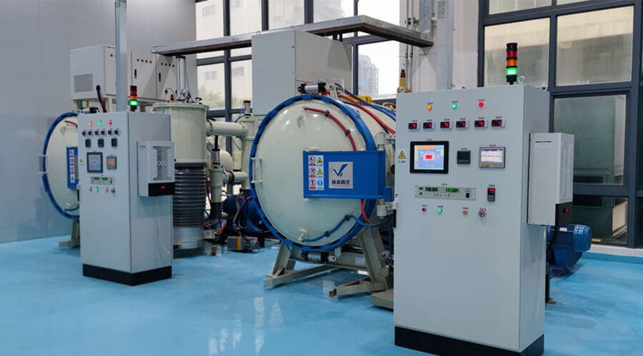
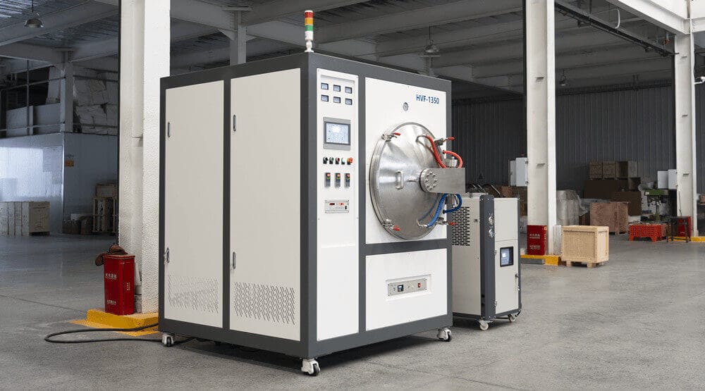
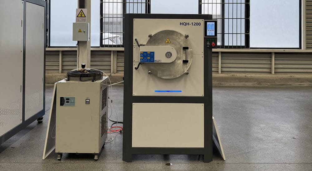
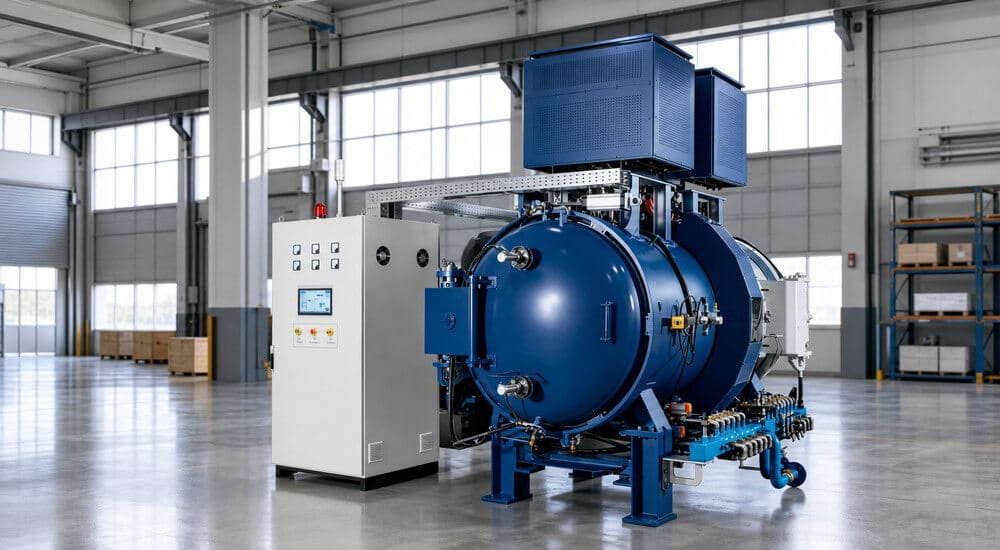
SYNHTE's Vacuum Sintering Furnace Systems cover multiple material and production routes. The Multipurpose Vacuum Sintering Furnace can be configured around debinding, high-temperature sintering, vacuum or selected atmosphere control and production data needs. The appropriate configuration depends on the actual material, load, setter, gas route, work-zone and acceptance plan; published model values do not replace application qualification.
Share the powder or feedstock specification, green-part and final drawings, binder/debinding route, target density and related properties, load and setter map, work-zone requirement, gas and vacuum assumptions, production volume, measurement methods, traceability needs, utilities and factory/site acceptance expectations. Ask how the proposed heating, vacuum, partial-pressure, gas-flow, cooling and data-recording configuration supports those inputs.

Agree the qualification boundary in the technical specification. Define which values are equipment acceptance tests, which belong to the material process, which production loads will be demonstrated and which records will be delivered. This separation prevents a nominal temperature, ultimate-vacuum value or empty-furnace test from being mistaken for final density qualification of the customer's production part.
Multipurpose Vacuum Sintering Furnace
The multipurpose platform is configured around the material system, debinding route, usable work zone, load presentation, vacuum or partial-pressure requirement, temperature program, cooling route and production evidence. Nominal temperature or chamber volume alone cannot establish that the real load will reach a repeatable final density. Equipment review should therefore include the complete qualification load, sensor and gas-control plan, data records and agreed acceptance tests.
What to include in your enquiry
- Exact material, incoming condition and governing drawing or specification
- Part, interface, fixture, stack and production-load drawings
- Required process outcome, acceptance methods, limits and sample locations
- Current process route, fixed variables, development questions and known risks
- Batch volume, data-retention needs, utilities, site interfaces and delivery requirements