
Surface Roughness in Vacuum Brazing: Wetting, Flow and Joint Quality
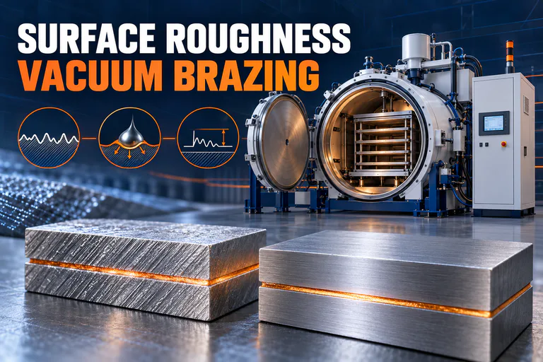
Surface roughness in vacuum brazing is a process variable, not a universal target. Texture can change apparent wetting, filler-metal spreading, capillary paths and the real contact condition inside a joint. Yet the same roughness value can behave differently when the base alloy, filler, oxide condition, machining lay, clearance or thermal cycle changes. A robust specification therefore defines how the surface is produced and measured, then qualifies it with the actual material–filler–joint system.
Why surface roughness changes a brazed joint
A nominally flat faying surface is a landscape of peaks, valleys and directional tool marks. When filler becomes liquid, that topography changes the local path available for spreading. Shallow connected grooves can provide extra routes along the interface, while deep asperities can obstruct a narrow gap, trap contamination or create pockets that the available filler does not fully occupy. The result is governed by scale: a texture that is small relative to the designed clearance can behave very differently from one whose peaks consume much of that clearance.
Roughness also changes the apparent contact area and the way a droplet sits on a surface. This does not mean that increasing area automatically improves metallurgical wetting. Oxide stability, surface chemistry and filler reactions still determine whether intimate contact can develop. In stainless steels, for example, passive films can be the controlling barrier even when the measured roughness looks favorable. In reactive or metallized systems, chemical reactions may dominate the final contact angle and reduce the influence of the original topography.
The practical lesson is to avoid the two simplistic rules “rougher is better” and “mirror polished is best.” Research across copper, stainless steel, ceramics and reactive alloy systems reports different trends and different preferred finishes. Those differences are expected because the tested fillers, temperatures, atmospheres, hold times and joint geometries are not interchangeable.
Machining lay can matter as much as the average value
Average roughness values such as Ra compress a complex profile into one number. Two surfaces can share the same Ra while one has long parallel grinding marks and the other has short, cross-cut features. The direction of those features relative to filler entry can change the easiest spreading path. A groove aligned with the intended flow may support directional movement; ridges that cross the path may increase resistance or produce uneven fronts. The effect must still be confirmed for the actual filler and gap, but lay direction should not be left undocumented.
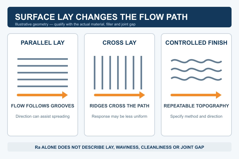
Waviness and flatness belong in the same conversation. Roughness describes relatively short-wavelength texture; it does not prove that two large parts form a uniform joint gap. A finely polished but bowed plate can produce a less consistent capillary space than a moderately machined, flat and well-supported surface. For long heat exchangers, manifolds or stacked assemblies, drawings and inspection plans should separate roughness, flatness, joint clearance and fixture control instead of asking one measurement to represent all four.
Roughness cannot compensate for clearance or cleanliness
Capillary flow depends on the complete channel formed by both faying surfaces. If the assembled gap is too tight, contact points and distorted areas can interrupt filler entry. If it is too wide for the chosen filler system, capillary pressure may be insufficient and the joint may require more filler than the design anticipated. Surface peaks effectively consume part of the local gap, so roughness and clearance must be specified together rather than on separate, unconnected drawings.
Cleanliness is equally fundamental. Oil, polishing compound, abrasive residue, fingerprints and oxide scale can remain inside valleys even when the profilometer result is within tolerance. Vacuum does not turn a contaminated surface into a prepared surface; heating can instead desorb or decompose residues at the same time that wetting should begin. The cleaning method therefore needs to follow the final machining step, and parts need controlled handling, drying and storage before assembly.
| Control | What it reveals | Why it changes the brazing result |
|---|---|---|
| Surface-production method | Grinding, milling, lapping, blasting or coating history | Different methods create different lay, damaged layers and residue risks even at similar Ra. |
| Joint clearance and flatness | The assembled capillary channel | Peaks, bow and fixture load can restrict entry or create locally wide gaps. |
| Final cleaning and handling | Whether the measured surface remains chemically available | Organic residue and oxides can dominate wetting regardless of profile. |
| Filler placement and thermal cycle | Where liquid filler starts and how long it can spread | A suitable texture cannot correct inadequate filler access or an unqualified liquidus window. |
How to specify and measure the surface condition
A useful production requirement names the base material and filler system, identifies the faying surfaces, defines the permitted finishing process and states where measurements are taken. It should also record the roughness parameter, instrument method, sampling length or cutoff, measurement direction and acceptance range. Without those details, two inspectors can measure the same part in different directions and produce values that are not comparable.
Ra is widely understood and useful for process control, but it may not describe isolated deep valleys or high peaks. Depending on the risk, a team may add a height parameter such as Rz, a profile trace, a visual comparator or a surface map. The objective is not to collect every available parameter. It is to capture the feature that can change filler access, interface continuity or part fit for this joint.
Measurement should normally occur after the final material-removal step and before any operation that intentionally changes the surface, such as plating or metallization. If chemical cleaning or coating changes the profile or surface energy, qualify that final condition separately. Keep calibration, stylus access, edge exclusion and part-temperature conditions consistent enough that trend data remains meaningful.
Qualify the material–filler–joint system, not a generic Ra number
Begin with a small, controlled matrix rather than adopting a roughness range from another alloy. Prepare coupons with documented finishing methods and lay directions while holding filler amount, clearance, cleaning, fixture load and cycle constant. A spread test can compare wetting behavior, but it cannot by itself prove production-joint strength or leak tightness. Section representative joints and examine filler continuity, voids, erosion and brittle phases where the application requires it.
Then move to the real production geometry. A stack of heat-exchanger assemblies contains many parallel joints, long flow distances, fixture contact points and large surface area. Those features introduce restrictions and gas loads that a flat coupon cannot reproduce. Use the coupon study to screen options, then release the finish only after a representative load meets the drawing and product-level acceptance plan.

Acceptance evidence should follow the failure mode. Leak-critical assemblies need a qualified leak test and a clear correlation to destructive sections during development. Structural joints may require tensile, shear or fatigue evidence. Dimensional assemblies need flatness and distortion checks. Process records should connect the finished surface lot, cleaning status, filler batch, load position and furnace cycle to the inspected result so that a roughness change is not evaluated in isolation.
What published studies can—and cannot—tell you
A 2025 study of vacuum-brazed SUS304 with BNi-2 filler reported strong results for a controlled grinding/polishing condition and showed that surface orientation affected joint strength. That is useful evidence that both texture and lay can matter, but it remains evidence for SUS304, BNi-2 and the tested cycle. It is not a transferable universal setting for copper, aluminum, ceramics or another nickel filler.
A separate stainless-steel wetting study found that sandblasting accelerated early spreading for its manganese-based filler, while nickel coating produced a notably lower wetting angle. The comparison illustrates why surface state includes chemistry and coating structure, not roughness alone. A broad review of brazing filler metals likewise concludes that the ideal texture can differ by parent metal and filler combination and that the available roughness literature is too sparse for one universal optimum.
Use published work to choose experimental boundaries and measurement methods. Use your own joint geometry and acceptance criteria to set the production specification.
Connect surface control to furnace and process control
Surface preparation will not remain repeatable if the furnace introduces an uncontrolled oxide, contamination or temperature condition. The relevant vacuum brazing furnace family should be selected around the base alloy, filler, cleanliness requirement, load size and acceptance evidence—not roughness alone. Pump-down behavior, hot-zone material, temperature uniformity, fixture arrangement and data recording all influence whether a prepared surface reaches the brazing window in a comparable condition.
For laboratory development and small controlled trials, a VTHB-334 multi-purpose vacuum furnace can support brazing process development when its work zone, load capacity and hot-zone configuration match the coupon or pilot assembly. Production equipment must then be qualified with the actual load, fixture mass and flow distances.

High-Temperature Vacuum Brazing Furnace
Configure the hot zone, vacuum package, work zone and controls around the material, filler, joint geometry and qualification plan.
- Graphite or molybdenum hot-zone routes for different cleanliness needs
- Batch loading for stainless steel, nickel alloy, copper, carbide and other qualified systems
- Cycle data and acceptance scope tied to representative production loads
Prepare a surface-and-joint qualification brief
For a focused furnace and process review, provide the base material and filler designation, faying-surface drawing, finish method and direction, measured roughness data, assembled clearance, cleaning sequence, fixture layout, representative load, brazing cycle and required leak, strength or dimensional acceptance.
Discuss your vacuum brazing applicationTechnical references
- Influence of Surface Roughness on the Strength and Microstructure of Vacuum Brazed SUS304 Using BNi-2 Filler Metal, Materials Transactions, 2025.
- Effect of the Surface States of 1Cr18Ni9Ti Stainless Steel on Mn-Based Brazing Alloy Wetting, Coatings, 2022.
- Brazing filler metals, International Materials Reviews, 2020.