
Aluminum Vacuum Brazing Vacuum Quality: Pressure, Cleanliness and Control

Vacuum quality affects aluminum vacuum brazing because it changes the oxygen, water vapor and contamination surrounding the joint while the filler alloy is melting. However, a single pressure reading cannot prove joint quality. The useful control method combines calibrated pressure measurement with leak tightness, pump-down behavior, load cleanliness, hot-cycle response and product acceptance results.
For aluminum plate-fin heat exchangers, cold plates and similar assemblies, this distinction matters. The same displayed pressure can represent a clean, tight furnace, a wet load that is still desorbing, or a gauge that is not reading the process space accurately. The process window should therefore be qualified for the actual alloy, filler, loaded geometry and furnace rather than copied from a universal pressure target.
Why one vacuum number is not a quality result
Absolute pressure is an important process variable, but it is an aggregate signal. It does not identify which gases remain, where they originate, how rapidly they are entering the chamber or whether the gauge is representative of the work zone. A stable reading at the pump inlet can coexist with a higher gas load near a large assembly if conductance through valves, baffles and piping is limited.
Temperature changes the interpretation again. Water and machining residues can desorb slowly during cold pump-down and more rapidly as the load heats. Magnesium-bearing filler systems also introduce vapor-phase behavior during brazing. A pressure value recorded before heating is therefore not equivalent to the pressure and gas composition around the joints near filler melting.
Use pressure as part of a traceable evidence chain: gauge condition, chamber configuration, cold and hot pump-down curves, rate-of-rise or leak-test results, load preparation and product inspection. This turns the vacuum record into engineering evidence rather than a pass/fail number detached from the actual load.
What vacuum quality changes at the aluminum joint
Aluminum carries a stable native oxide film. Vacuum alone should not be described as simply removing that film. In common aluminum vacuum-brazing systems, magnesium in the filler or process system can help disrupt the oxide, improve wetting and act as a getter for residual oxygen and water vapor. Published work on aluminum-silicon-magnesium filler metals describes this coupled role of magnesium vapor during heating.
The practical implication is that pressure, gas composition, surface preparation and filler chemistry interact. A cleaner and tighter environment reduces the supply of oxidizing and contaminating species, but it cannot correct incompatible alloys, poor joint clearance, damaged clad, trapped cleaning fluid or an unsuitable thermal cycle. Conversely, a well-prepared assembly can still fail if leakage, moisture or pump contamination overwhelms the qualified process environment.
Very aggressive evacuation is not automatically better when it is separated from the complete recipe. Magnesium evaporation depends on temperature, time, alloy condition and pressure. Excessive vapor transport can contribute to deposition on furnace surfaces and change the balance available at the joint. Set pressure limits together with the filler system and hot-cycle qualification instead of tightening the setpoint in isolation.
How poor vacuum quality appears in product evidence
A high or unstable gas load may contribute to poor wetting, incomplete filler flow, internal voids, discoloration or contamination, but these symptoms are not unique to vacuum performance. Joint clearance, filler placement, surface condition, local temperature and fixture restraint can produce similar results. Diagnose from correlated evidence rather than assigning every defect to the pump.
| Observed evidence | Vacuum-related question | Confirmation needed |
|---|---|---|
| Poor or discontinuous wetting | Was oxygen, moisture or contamination elevated near filler melting? | Pressure trace, residual-gas pattern where available, surface-preparation record and thermal data. |
| Porosity or leak-test failure | Was gas trapped by an unvented feature or released from the load? | Sectioned samples, vent-path review, cold/hot pump-down comparison and calibrated leak test. |
| Heavy furnace deposits | Did vapor transport or pump backstreaming change from the baseline? | Deposit location, process history, pump protection checks and alloy/filler review. |
| Load-to-load variation | Does pump-down change with cleaning, storage time, mass or surface area? | Comparable load records, lot traceability, loaded pressure curves and product results. |
The table is a diagnostic cross-check, not a defect dictionary. Release decisions should connect the pressure evidence with a defined inspection plan such as leak testing, dimensional verification, metallography or destructive sampling appropriate to the product.
Read pump-down shape and hot-cycle response
A pressure trend can reveal more than the final value. A persistent plateau may justify a leak investigation. A long decay tail can be consistent with moisture or desorption from a large surface area. A clean, tight reference load should produce a repeatable curve for the same chamber condition, pumping configuration and gauge location. These signatures are diagnostic prompts, not universal acceptance limits.
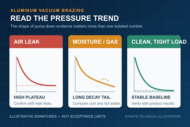
Compare at least three states when establishing a baseline: an empty clean chamber, a cold representative load and the same load through the hot cycle. Record valve positions, pump configuration, gauge identity and the point in the recipe where each value is evaluated. If the pressure rises during heating, relate the event to temperature and time rather than treating the peak as an isolated alarm.
Use a calibrated gauge chain that covers the working range. Cross-check overlapping sensors, control contamination at the gauge port and document as-found deviations. A plausible display is not evidence that the pressure at the load is correct. The existing vacuum gauge calibration guide explains how to connect sensor selection and cross-checking to furnace decisions.
Set the vacuum process window without a universal magic number
The source article cites a very high-vacuum range as ideal, but that number should not be copied as a universal requirement. Aluminum brazing practice varies with base alloy, clad or separate filler, magnesium content, product geometry, furnace size, pump train, gauge type and the stage of the cycle being measured. A chamber base pressure, a pressure before heating and a pressure near brazing temperature are different specifications.
Define the window from product evidence. Start with a technically credible furnace condition, then qualify representative loads at the intended production extremes: minimum and maximum mass, high surface area, different fixture configurations and the longest permitted storage time after cleaning. Record pressure and temperature together. Evaluate joint fill, leakage, dimensions and any application-specific properties.
Set action limits only after repeatable acceptable loads establish the normal distribution. Include rules for a slower pump-down, a hot pressure excursion, gauge disagreement and a failed rate-of-rise check. The limit should trigger a defined investigation or hold, not merely encourage the operator to continue pumping until the display reaches a preferred number.
Qualify the furnace with the real production load
Large aluminum heat-exchanger loads present far more surface area, trapped volume and thermal mass than an empty-chamber test. The load arrangement also changes gas flow paths and can restrict radiant exposure. A pressure specification is meaningful only when the furnace can achieve it repeatably with the qualified fixture, carriers and production loading pattern.

Use the real loaded envelope when assessing pumping speed and conductance. The effective speed at the chamber depends on the complete path between work zone and pump, not the pump nameplate alone. Review baffles, isolation valves, foreline condition, diffusion-pump protection where used and cold-trap or oil-backstreaming controls. The diffusion-pump design and upgrade guide provides a separate hardware-focused checklist.
After maintenance or a major load change, compare the new pressure trace with the qualified baseline and confirm product results. Pump maintenance, chamber cleaning, new fixtures, revised part cleaning and different filler lots can all shift the gas load. Change control keeps a gradual drift from becoming an unexplained quality event.
Match aluminum brazing equipment to the evidence plan
When comparing vacuum brazing furnace systems, specify the required pressure range, loaded pump-down time, process temperature, work-zone dimensions and production acceptance method. Ask how the gauge ports, pump train, valve conductance, contamination protection and control records support the qualified process.
For plate-fin heat exchangers and cold plates, the High Vacuum Aluminum Brazing Furnace is the relevant SYNHTE equipment family. Furnace selection still has to be tied to the actual filler system, load cleanliness, fixture arrangement and product qualification. Equipment capability creates the controlled environment; it does not replace the brazing procedure.

High Vacuum Aluminum Brazing Furnace
Review the furnace as a complete process system: usable work zone, loaded pump-down performance, pressure measurement, temperature control, pump protection and production data recording.
What to include in a vacuum-quality review
- Base alloy, filler or clad specification, magnesium content and joint geometry.
- Part cleanliness route, drying and storage controls, fixture materials and complete loaded dimensions.
- Cold and hot pressure traces, gauge types and locations, leak-test or rate-of-rise records and pump configuration.
- Process temperatures, hold times, production rate and acceptance evidence such as leak testing, dimensions or metallography.
Send the application requirements to SYNHTE so the vacuum system, loaded cycle and qualification plan can be reviewed together.
Technical references
- Bai et al.: 6063 aluminum alloy joints vacuum brazed with aluminum-silicon-magnesium filler — magnesium vapor, oxide disruption, wetting and joint microstructure.
- Study of magnesium loss in an aluminum-magnesium-silicon alloy — measured magnesium evaporation and partial-pressure behavior.
- NASA technical report on aluminum alloy vacuum brazing — historical experimental evidence on magnesium-assisted flow and wettability.