
Stainless Steel Oil Cooler Vacuum Brazing: Copper Filler and Load Qualification
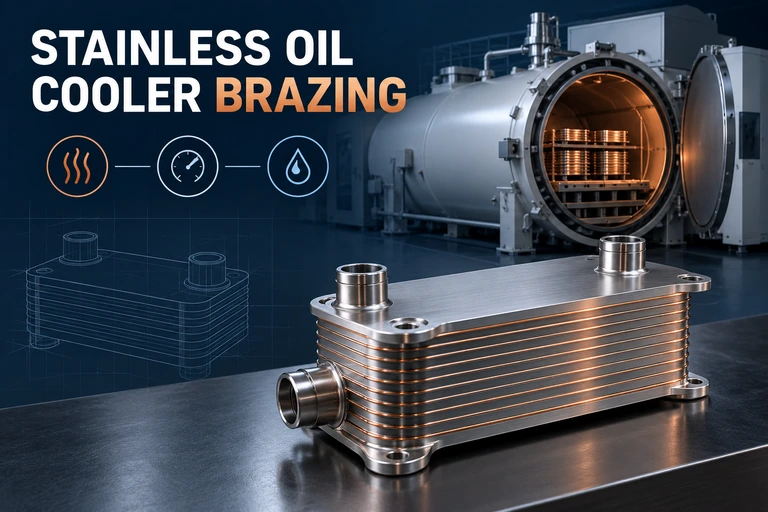
Define the assembly before defining the cycle
A stacked-plate oil cooler combines many thin stainless interfaces, headers or end plates, and tubular ports. That geometry creates a large cumulative joint length and many opportunities for trapped gas, uneven filler flow, distortion, or an internal leak path. The process specification therefore needs the exact component drawing revision, stainless grade and condition, surface preparation, filler designation, filler form, and service requirements. “Stainless steel plus copper” is not a complete brazing specification.
Start with the required outcome. Record the working fluid, design pressure, permitted external and internal leakage, dimensional limits, cleanliness requirement, and any customer or industry specification. Identify joints that separate two fluid circuits, joints that are difficult to inspect after brazing, and dimensions that control final installation. These become the critical features for coupon design, thermocouple placement, inspection, and release.
Do not transfer a successful recipe from another cooler solely because the outside dimensions look similar. Plate count, sheet thickness, port mass, joint area, filler quantity, fixture contact, and load density all affect heating and cooling. A qualified family needs documented boundaries for these variables.
Qualify the copper filler as a controlled material
Copper-based filler can create clean, ductile joints in suitable stainless assemblies, but the usable process window depends on the actual filler specification and the base-metal system. Verify the supplier designation, chemistry or certificate, product form, dimensions or mass, lot traceability, storage condition, and placement method. Foil, shim, wire, ring, paste, or plated filler can behave differently because the exposed surface area, binder content, placement repeatability, and risk of displacement are different.
Filler quantity should be tied to the joint design and verified on representative sections or development assemblies. Too little filler can leave incomplete paths; excessive filler can pool, bridge passages, migrate to unwanted surfaces, or mask a poorly controlled gap. Where paste is used, its vehicle removal behavior must be proven rather than assumed. Where preforms are used, the drawing or work instruction should show their exact location and retention method.
A furnace setpoint copied from a general chart is not a qualification. Use the filler supplier’s current technical data together with the applicable brazing specification and the assembly’s demonstrated thermal behavior. Confirm that the selected range produces complete wetting without unacceptable base-metal effects, filler loss, erosion, distortion, or contamination of the furnace system.
Design continuous joint and vent paths
Capillary joints need a controlled clearance at brazing temperature, clean mating surfaces, and a continuous path for filler flow. Oil-cooler plate stacks also need a way for displaced gas and volatilized residue to leave the joint. A sealed pocket can behave like a virtual leak during heating and can block filler from reaching a critical area. Review embossments, plate contact, port-to-header transitions, blind volumes, and the sequence in which paths close as filler flows.
Joint clearance must be evaluated in the hot condition. Stainless parts, copper filler, fixtures, and massive ports do not heat or expand identically. Burrs, waviness, stamping variation, oxide, handling damage, or excessive clamping can locally close a designed gap. Conversely, a fixture that provides too little control can allow plates to separate or slide. Use dimensional studies, metallographic sections, and representative leak results to establish the acceptable assembly range.
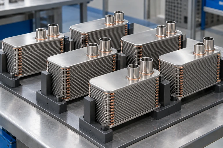
The fixture should locate the stack without creating an unintended heat sink or preventing natural movement. Apply only the loading needed to maintain joint contact and geometry through the cycle. Record fixture material, contact locations, mass, condition, and reuse limits because fixture growth, contamination, or distortion can change a previously stable process.
Treat the production load as part of the qualified process
A full furnace load is not simply several single-part trials placed together. Tier spacing, distance from heating elements or gas nozzles, shielding by neighboring parts, support rails, fixture mass, and total exposed filler area can create different thermal and vacuum behavior. Define the load pattern with photographs or a load drawing, including part orientation, tier count, spacing, fixture locations, and permitted empty positions.
Place load thermocouples or qualified temperature sensors at locations chosen from risk: a heavy port or shielded inner position may be slow to heat, while an exposed edge or lightly loaded position may be fast. Development work should find both the likely cold and hot joints. The control thermocouple alone cannot prove that every braze interface received the same thermal exposure.
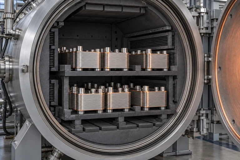
When load size changes, compare the actual heat-up, equalization, vacuum response, and cooling behavior with the qualified range. A fixed time calculated only from gross load weight or a simple diameter ratio cannot replace measured load evidence. The same rule applies when a fixture design, part orientation, furnace zone, or tier arrangement changes.
Build the thermal cycle from joint evidence
The cycle normally needs controlled heating, adequate removal of moisture and process residues, temperature equalization, a brazing stage, and controlled cooling. The exact ramps, holds, pressure transitions, and brazing range are process-specific. Develop them from the approved filler data, the relevant specification, furnace capability, and instrumented trials on representative assemblies.
During development, compare the hottest and coldest critical-joint temperatures rather than relying on chamber temperature alone. Record the time each location spends within the approved window. A long dwell can increase filler migration, grain growth, distortion, or interaction with the base metal; a short dwell can leave incomplete flow at shielded joints. The objective is sufficient joint formation throughout the load with the least unnecessary exposure.
Thermocouple attachment and routing are part of the evidence. Define sensor type, calibration status, attachment location, attachment method, and whether the sensor measures a representative surface or a true joint location. Preserve the chart and load map with the batch record so a later leak result can be linked back to the actual thermal history.
Control vacuum, partial pressure, and furnace contamination
Vacuum supports oxide control and removal of gaseous products, but a single displayed pressure does not describe the entire atmosphere. Moisture, binder products, hydrocarbons, air leakage, or volatilized species can produce different joint outcomes at a similar total pressure. Trend pressure against temperature, pump and valve state, gas admission, and load thermocouples. Compare the trace with an approved reference load rather than judging one endpoint value.
For assemblies with a large exposed filler area, confirm whether the approved process uses high vacuum throughout or a controlled inert partial pressure during a specific stage. That decision must follow the filler, base materials, furnace design, and qualified procedure. Do not introduce an arbitrary gas pressure to suppress vaporization: gas purity, dew point, flow path, pumping transition, and cooling duty all matter.
Protect the furnace as well as the work. Review filler collection, shields, hot-zone compatibility, pump protection, and cleaning intervals. If copper or process residue appears on cold surfaces, seals, or pumping components, investigate the transport mechanism and exposed filler area before simply shortening the cycle. Cross-contamination risk should be considered when the same furnace processes other alloys or cleanliness-sensitive loads.
Control cooling and unloading to protect the braze
The joint is not finished when peak temperature ends. Uneven cooling can distort a thin plate stack, load ports in bending, or create residual stress across a large brazed area. Define when vacuum cooling, inert-gas backfill, circulation, or fan cooling begins and verify that the load remains within furnace and product limits. Gas quality at the point of use matters because moisture or oxygen introduced during cooling can discolor clean stainless surfaces.
Base unloading on a qualified load-temperature limit, not only on the controller or elapsed time. Heavy ports and shielded inner stacks can remain hotter than exposed surfaces. Record the actual unloading condition and protect the assembly from contamination or rapid local cooling during handling. If a different load density changes cooling time or distortion, treat it as a process change requiring review.
Release the cooler with leak, dimensional, and joint evidence
Visual appearance alone cannot demonstrate a leak-tight oil cooler. The acceptance plan should connect each critical function to a test method, calibrated equipment, acceptance limit, sample plan, and responsible authority. Use the product drawing, customer requirement, and applicable code or specification to define those limits; do not import a generic leak value from another assembly.
| Requirement | Typical evidence | What it confirms |
|---|---|---|
| External and circuit-to-circuit leak tightness | Approved pressure-decay, bubble, tracer-gas, or mass-spectrometer test | The finished fluid boundaries meet the specified test condition |
| Joint formation | Representative section, coupon, radiographic method, or validated indirect inspection | Wetting, filler distribution, and unacceptable discontinuities are controlled |
| Dimensional stability | Stack height, flatness, port position, envelope, and fixture-release checks | The cooler can be installed and loaded as designed |
| Process consistency | Load map, thermal records, vacuum/gas trace, material lots, and operator sign-off | The batch stayed inside the qualified process |
Classify imperfections separately from acceptance. ISO 18279:2023 provides a classification system for imperfections in brazed joints, but classification does not automatically define product acceptance. The drawing, contract, application risk, and qualified inspection plan must state what is permitted.
Minimum qualification record
- base-metal and filler specifications, lots, forms, and storage status;
- joint drawings, vent paths, filler placement, and assembly measurements;
- fixture identification, load arrangement, and representative sensor map;
- complete temperature, pressure, valve, gas, and cooling records;
- leak, dimensional, and joint-quality results linked to the trial load;
- approved operating window and change-control boundaries.
Match furnace capability to the qualified load
Oil-cooler production needs more than a chamber large enough for the fixture. Review hot-zone usable volume, temperature uniformity, load thermocouple capacity, pumping behavior with the real assembly, partial-pressure and gas-cooling controls, contamination management, data recording, and maintenance access. See Vacuum Brazing Furnace Systems and the High-Temperature Vacuum Brazing Furnace for equipment context.
What to include in your enquiry
Share the cooler drawing and materials, plate count and envelope, stainless grades, copper filler designation and form, target batch size, fixture concept, current cycle traces, leak and dimensional requirements, available utilities, and any failed sections or load-position patterns. Remove customer-confidential identifiers if necessary.