
Nickel-Based Superalloy Vacuum Brazing: Process Qualification Controls

Nickel-based superalloy vacuum brazing should be qualified as a defined joint-and-process system. Fix the base-metal condition, joint geometry, selected filler classification and form, surface preparation, assembly and fixture method, production load map, furnace and hot zone, vacuum and thermal-cycle variables, cooling route, inspection method and acceptance limits. Release production only when representative samples and parts demonstrate the required joint quality and service-relevant properties under the governing specification.
Define the joint and service requirement before choosing a cycle
Start with the assembly requirement, not a familiar filler or furnace recipe. Record the exact nickel-based alloy and product form, heat-treatment or coating condition, mating materials, joint geometry, designed clearance, load path, service temperature, environment, dimensional limits, inspection access and governing customer, industry or internal specification. Nickel-based superalloys are not one interchangeable material family; a procedure qualified for one base-metal condition, filler and joint may not be transferable to another without engineering review.
Define what the brazed joint must do and which failure modes matter. A static seal, thin honeycomb attachment, internal passage, structural lap joint and repair feature create different priorities for gap control, filler volume, erosion risk, distortion, leak integrity, strength and inspection. The acceptance plan should separate visual workmanship from functional evidence. A smooth external fillet may not prove complete internal flow, while a small cosmetic variation may be acceptable if the controlling specification and qualified evidence allow it.
Create a procedure qualification record that links drawing revision, base-metal lots, filler classification and lot, filler form and placement, cleaning method, assembly time limits, fixture identity, furnace and hot-zone identity, approved load map, thermal-program revision, sensor and vacuum records, cooling route, inspection and test results. This traceable definition is the baseline for production and for later decisions about whether a change is minor, requires engineering review or demands requalification.
Control base metal, surface condition and filler placement
Surface preparation must produce a repeatable condition compatible with the selected base metal, filler and procedure. Control machining residue, oils, marking materials, oxide or scale condition, cleaning chemistry, rinse and drying, glove or tool contact, storage environment and the maximum allowed time between final cleaning and furnace loading. Do not replace a defined method with the instruction “clean thoroughly.” Residue that is invisible before heating can still affect outgassing, wetting or joint inspection.
Filler selection belongs to engineering qualification. Use the classification, chemistry, form and supplier documentation required by the approved design and procedure, and evaluate compatibility with the base metal, brazing temperature range, service environment and required joint properties. AWS A5.8 provides brazing filler-metal classifications, including nickel-group and vacuum-service categories, but a classification does not by itself approve a filler for every superalloy or service condition. Control foil, paste, powder, preform or other filler form, applied amount, placement and lot traceability.
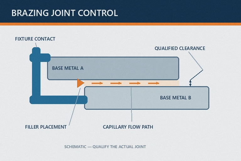
Joint clearance and filler movement depend on the complete system, including geometry, surface condition, thermal expansion, fixture restraint, filler behavior and thermal cycle. Measure or verify the dimensions that establish the joint before assembly, then check fixture contact and orientation. Excess filler can move into an unintended region or make inspection difficult; insufficient or discontinuous placement can leave incomplete coverage. Development changes should be isolated and documented rather than altering clearance, filler amount and temperature in the same trial.
Qualify the thermal cycle and production load geometry
The furnace cycle must establish the intended joint without creating unacceptable base-metal, filler or dimensional effects. Define the pump-down and heating sequence, relevant vacuum or partial-pressure controls, temperature measurement and uniformity basis, approach to the brazing interval, hold logic, cooling route and deviation rules. The qualified values come from the selected materials, filler supplier data, engineering development and governing specification. Avoid publishing one temperature as “the” nickel-superalloy brazing recipe.
Load geometry is part of the procedure. A lightly loaded qualification fixture may heat, outgas and cool differently from a dense production assembly. Record fixture material and mass, part spacing, orientation, center and edge positions, shielding, thermal mass and the relationship between load sensors and critical joints when load sensing is required. Use representative parts or deliberately designed qualification samples at positions that challenge the approved work zone. Preserve position identity through inspection.
| Control group | Record in qualification | Primary risk addressed |
|---|---|---|
| Assembly | Base-metal state, clearance, filler, preparation and fixture | Inconsistent wetting, flow, fit or contamination |
| Load | Position map, mass, spacing, orientation and sensor relationship | Unseen center-to-edge or shielded-joint variation |
| Furnace cycle | Vacuum history, thermal execution, cooling and deviations | Nonrepeatable joint formation or base-metal exposure |
| Acceptance | Inspection method, sample location, results and disposition | Releasing a load on appearance alone |
Run confirmation loads that include normal production variation and define the permissible load envelope. If multiple assembly families will share one procedure, demonstrate why the selected samples cover the important clearance, mass, geometry and inspection risks. Recipe access, data retention and alarm review should be settled before production begins.
Tie inspection evidence to joint risk and load position
Build the inspection plan from the drawing, service risk and governing specification. Depending on the assembly, evidence may include visual examination, dimensional inspection, leak testing, radiography or another nondestructive method, metallographic sectioning, joint-clearance or filler-distribution assessment, mechanical testing, hardness or base-metal checks, and process-record review. Not every method suits every geometry, and no single generic test proves all joint functions. Define method, acceptance limits, sampling, specimen location and disposition before the qualification load is run.
Preserve joint and load position identity. Compare center, edge, top, bottom, exposed and shielded regions when those locations may experience different thermal or vacuum conditions. If destructive specimens or witness coupons are used, show how they represent the production joint, base-metal condition, filler placement, fixture restraint and thermal mass. A coupon can support qualification evidence, but it should not replace production-part inspection where the joint geometry or failure risk is materially different.
When a result fails, protect the evidence before changing the recipe. Retain the failed joint or section, photographs, inspection data, filler and base-metal lots, cleaning records, assembly timing, fixture identity, load map, complete cycle record and alarm history. Classify whether the observation is associated with surface condition, clearance, filler amount or location, fixture movement, incomplete flow, erosion, porosity, cracking, distortion, leakage, base-metal change or test variation. Corrective action should follow the supported mechanism; raising temperature or adding filler without that diagnosis can trade one problem for another.
Match the furnace to nickel-superalloy brazing work
SYNHTE's Vacuum Brazing Furnace range includes a High-Temperature Vacuum Brazing Furnace described for high-vacuum joining of nickel-based and other high-performance alloys. The current product page lists configurable graphite or molybdenum hot zones, pumping systems, protective-gas options, programmable controls and cooling choices. The useful configuration must be selected against the base metal, filler, cleanliness target, work-zone size, load mass, fixture, temperature-uniformity evidence, vacuum response, cooling and data requirements.
If the application is actually a pressure-assisted diffusion-bonding route or a hybrid development program rather than conventional filler-metal capillary brazing, review the Vacuum Diffusion Bonding & Brazing Furnace separately. Do not merge the two process intents in a request for quotation. Provide alloy specifications, joint and assembly drawings, filler classification and form, preparation procedure, fixture and production-load concept, required process records, inspection and qualification plan, expected volume, utilities and facility constraints. Ask the supplier to explain how the proposed system will support the recorded procedure rather than requesting a furnace by maximum temperature alone.
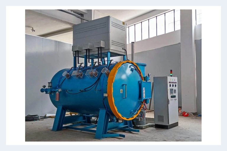
High-Temperature Vacuum Brazing Furnace
This furnace family supports programmable high-vacuum brazing of nickel-based and other high-performance alloys with configurable hot-zone, pumping, gas and cooling systems. Equipment capability must be evaluated against the specific base metal, filler, assembly, load, qualification procedure and facility requirements.
What to include in your enquiry
- Exact material, feedstock or filler identification and governing specification
- Part, joint, fixture, tray and representative production-load drawings
- Current process route, fixed variables, development questions and known failure risks
- Required dimensions, properties, inspection methods, sampling and acceptance limits
- Expected batch volume, throughput, data-retention needs, utilities and site constraints