info@synthe-corp.com

+86-155-3785-7393

Double-chamber vacuum hardening system

Vacuum Oil Quenching Furnace

SYNHTE double-chamber systems combine clean vacuum heating with controlled oil quenching for tool steels, mold steels, high-speed steels and alloy-steel parts. Chamber size, hot zone, transfer, oil circulation and controls are matched to your load and production target.

Double chamberRapid load transferControlled oil condition
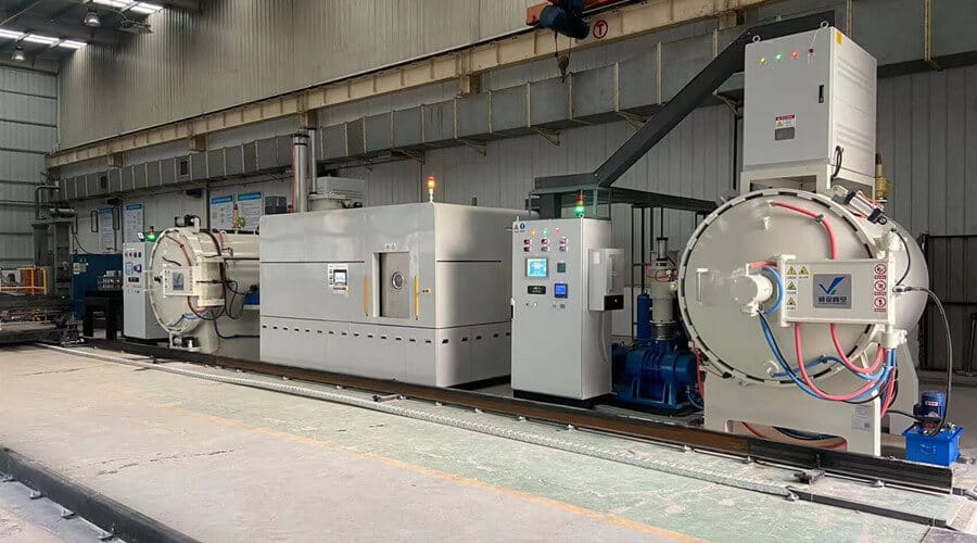
Double-chamber vacuum oil quenching furnace production line with heating chamber, quench chamber and control cabinets
Double-chamber production system with dedicated heating, oil-quench, vacuum, circulation and control modules.
1320°CMaximum temperature
±5°CTemperature uniformity
4 × 10⁻¹ PaUltimate vacuum
100–800 kgLoading range
01 / Application fit

Furnace selection built around your parts

Material grade, geometry, prior condition, target hardness, dimensional tolerance and production load determine the heating, transfer and oil-quench configuration.

01

Material response

Steel grade, starting condition and hardenability establish the heating and cooling window for tool, mold, high-speed, spring, stainless and alloy steels.

02

Section and geometry

Maximum section, bores, teeth, sharp transitions and fixture contact define load support and dimensional-control priorities.

03

Quench objective

Target hardness, metallographic checks, surface condition and dimensional tolerance shape the qualified process window.

04

Production load

Basket envelope, batch mass, load pattern, cycle target and annual volume determine transfer capacity and oil circulation.

Best suited to: parts requiring higher cooling severity than the selected gas-quench route while retaining clean vacuum heating and controlled transfer into oil. Process trials can validate hardness, surface condition and dimensional response on the production load.
02 / Process architecture

Separate clean heating from controlled oil quenching

The double-chamber arrangement keeps the heating hot zone and oil-quench zone functionally separate. The load is heated under vacuum, transferred through the interlocked route, submerged into conditioned oil and released only after the programmed sequence is complete.

  1. Load and evacuateBasket, fixture and part layout are checked against the approved load map before the heating chamber is evacuated.
  2. Preheat, heat and soakProgrammable segments manage the selected steel and section while vacuum, temperature and alarms are recorded.
  3. Interlocked rapid transferThe transfer arrangement and gate sequence are selected to control the interval between heating and immersion.
  4. Oil quench and circulationOil temperature, agitation or circulation, load position and dwell are managed as part of the qualified process window.
  5. Drain, cool and unloadThe release condition, residual-oil handling and next operation are agreed for the part family and plant workflow.
Diagram showing transferred load, oil flow, filter return and oil sampling point in a vacuum oil quenching system
Oil temperature, circulation, filtration and condition monitoring belong in the same process record as the furnace recipe and inspected part result.
03 / Cooling-route boundary

Oil quenching for higher cooling severity

Oil quenching supports steels, sections and load densities that require a stronger cooling response. Gas cooling remains available for applications prioritizing clean unloading and adjustable convection.

Oil-quench route

For steel, section and load combinations requiring greater cooling severity.

  • Double-chamber separation and controlled transfer
  • Controlled oil temperature, circulation and filtration
  • Integrated drainage, cleaning and oil-change planning

Gas-quench route

For suitable alloys and loads requiring clean, adjustable convective cooling.

  • Gas type, pressure, flow distribution and heat-exchanger capacity
  • Clean unloading with less downstream oil removal
  • Part-level hardness and dimensional validation
04 / Furnace evidence

Hot-zone design and process control are specified together

Graphite or molybdenum hot zones combine with controlled oil temperature and circulation, interlocked operation, programmable recipes, alarms and process records in one production system.

Interior view of a vacuum furnace hot zone with heating elements and load support structure
Heating-zone configurationGraphite or molybdenum options support different operating temperatures, cleanliness requirements, load chemistries and maintenance strategies.
Industrial vacuum furnace control cabinet with touchscreen, instruments, status lights and safety controls
Controls and process recordsPLC and touchscreen control combine recipes, measured values, alarms, interlocks and operator records.

Oil temperature and flow

Oil type, operating window, circulation or agitation, filtration and sampling are integrated into the quench system.

Vacuum and transfer

The pumping package, chamber cleanliness and load-transfer sequence are matched to the production cycle.

Traceability

Recipe versions, temperature and pressure records, alarms and operator actions support qualified-load traceability.

05 / VTO configurations

VTO configurations for production loads from 100 to 800 kg

Five VTO configurations cover work zones from 300 × 300 × 450 mm to 700 × 700 × 1200 mm. Custom load, utility, cycle and acceptance requirements are incorporated into the project proposal.

VTO Vacuum Oil Quenching Furnace configuration range
ModelEffective work zone W × H × LBatch loadHeating powerMax. temperature
VTO-335300 × 300 × 450 mm100 kg50 kW1320°C
VTO-446400 × 400 × 600 mm200 kg65 kW1320°C
VTO-557500 × 500 × 700 mm300 kg100 kW1320°C
VTO-669600 × 600 × 900 mm500 kg150 kW1320°C
VTO-7712700 × 700 × 1200 mm800 kg200 kW1320°C

Across the VTO range: ±1°C control accuracy, 4 × 10⁻¹ Pa ultimate vacuum, 0.5 Pa/h pressure-rise data and an optional 2 bar gas-cooling route. Final values and supplied scope are confirmed in the technical proposal.

Hot zoneGraphite or molybdenum options matched to process and cleanliness needs.
Oil systemAgitation or circulation, filtration and temperature-control arrangement.
Load transferAutomatic mechanism and interlocks sized around the approved load.
Vacuum packagePumping configuration matched to cleanliness and cycle objectives.
FixturesCustom baskets, trays and loading equipment for the part family.
ControlsPLC, touchscreen, recipes, records, alarms and agreed interfaces.
06 / FAT and SAT

FAT and SAT aligned with your acceptance criteria

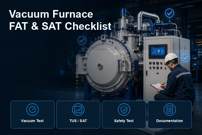
FAT and SAT packages can cover the production load, instrumentation, test methods, pass criteria, documentation, training and retained process records.

Work-zone verificationAgreed temperature uniformity method, sensor layout, setpoints and report format.
Vacuum performanceUltimate pressure, pressure-rise method, timing and instrumentation scope.
Transfer sequenceInterlocks, transfer timing, load handling and recovery from abnormal conditions.
Oil systemTemperature window, circulation or agitation, filtration and alarm checks.
Process trialDefined material, fixture, load map, recipe and pre-agreed inspection evidence.
DocumentationDrawings, manuals, certificates in scope, records, training and handover list.
07 / Engineering enquiry

Configure the furnace around your production load

Our engineering team uses your material, part, batch, oil, throughput and site requirements to prepare the chamber, hot-zone, vacuum and control configuration.

RFQ 01Material

Steel grade, starting condition and prior heat treatment.

RFQ 02Part geometry

Maximum section, critical dimensions and distortion limit.

RFQ 03Acceptance result

Hardness, metallography, surface and inspection method.

RFQ 04Batch envelope

Basket size, total mass, load pattern and fixture concept.

RFQ 05Oil parameters

Oil type, temperature limits, quench severity and change control.

RFQ 06Production target

Cycle time, annual volume, shifts and loading method.

RFQ 07Site interfaces

Utilities, floor plan, exhaust, cooling water and local requirements.

RFQ 08Delivery evidence

FAT/SAT, records, documents, training and handover scope.

08 / Related equipment

Compare related vacuum heat-treatment systems

Which materials can be processed in a vacuum oil quenching furnace?

The VTO range supports tool steel, mold steel, high-speed steel, spring steel, stainless steel and other alloy steels, with the process configured for the grade, starting condition, section, geometry and target properties.

How are surface condition and distortion controlled?

Vacuum heating, load support, recipe control, transfer timing and oil condition work together to control the result. Trial loads establish the process window for your material, geometry and inspection requirements.

Can gas cooling be added to the VTO family?

A 2 bar gas-cooling option is available on configured VTO systems, allowing the cooling route to be matched to different materials and production requirements.

What determines the correct VTO model?

Model selection considers fixture envelope, batch mass, heating power, transfer arrangement, production cycle, oil circulation, utilities and acceptance scope.

Engineering configuration for your production load

Provide the material grade, part drawing, batch envelope, mass, target hardness, dimensional limit, oil requirements and production volume for a tailored technical proposal.

Technical download

VTO Vacuum Oil Quenching Furnace Specifications

Download the current reference document or compare all available SYNHTE technical resources.

Contact Us

15+ Years Industrial Experience

Annual output 200+

CE & ISO Certified

Reply within 12 hours

Professional technical support

Free consultation service