
Oil Cooler Vacuum Brazing Defects: Triage Before Rework or Scrap
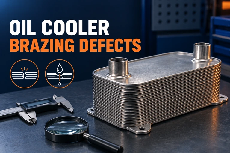
Oil cooler vacuum brazing defects should be separated into observations, confirmed causes and acceptance decisions. Hold the affected batch, preserve its load and cycle evidence, and distinguish joint leakage, dimensional damage, fixture adhesion and surface contamination. Rework is a controlled engineering decision, not an automatic hotter repeat cycle; a cleaner surface does not prove that the cooler is fit for release.
This guide concerns stainless-steel plate-stack oil coolers, particularly assemblies using copper filler. It addresses the investigation after a rejected batch rather than defining an initial production recipe. For the wider assembly, filler and load-development framework, see stainless steel oil cooler vacuum brazing qualification. Keep aluminum cooler procedures separate because their materials and thermal limits are different.
Hold the batch and preserve the first evidence
Begin with containment. Identify the furnace run, cooler serial or batch identities, material and filler lots, fixture, loading positions and recipe revision. Keep the suspect units separate from accepted stock. Retain comparison units from apparently unaffected positions where practical. A defect concentrated beside one support or at one load edge can suggest a different investigation from a fault spread throughout the batch.
Before polishing, cleaning, straightening or disassembling a failed cooler, photograph the surfaces and record the first inspection results. Preserve orientation, the location of any leak or deposit, and the relationship to ports, plate edges and fixture contacts. An attempted cosmetic improvement can remove evidence of transport, local contact or residue without correcting the underlying joint.
Capture temperature, pressure, gas-admission, cooling and alarm histories, including the events before the observed deviation. Record any recent change in preparation, filler application, maintenance or loading. If an equipment alarm or utility loss is involved, follow the furnace manufacturer's and site's approved emergency procedure. Do not force valves, bypass interlocks or improvise a pressure-and-temperature sequence to save the batch. Product disposition can wait until the equipment is safe.
Classify oil cooler vacuum brazing defects by evidence
Name what is actually observed before assigning a cause. A pale plate edge may indicate an unfilled region, a difference in wetting or a surface condition, but it is not a measurement of internal bonded area. Similarly, a black spot does not by itself establish that pump oil caused the fault, and a visually clean cooler can still leak between circuits.
| Observation | Evidence to collect | Decision boundary |
|---|---|---|
| External leak or communication between circuits | Leak location, test conditions, instrument checks and representative joint examination. | Use the specified fluid-boundary acceptance requirement; appearance cannot replace the test. |
| Pale edge, local unfilled joint or excessive filler deposit | Hot-gap basis, filler placement, relevant load temperatures and selected sections. | Determine whether the joint function and remaining material meet the drawing before considering repair. |
| Warped stack, shifted port, dent or fixture adhesion | Pre/post dimensions, support contact map, fixture condition and handling history. | Evaluate geometry and any damage from release or straightening, not only overall visual symmetry. |
| Yellow, blue, grey or black surface | Deposit location, process phase, gas and vacuum history, equipment condition and appropriate surface analysis. | Establish the cause and product consequence; colour alone neither approves nor condemns the joint. |
ISO 18279:2023 classifies imperfections in brazed joints and provides guidance on quality levels. It does not establish application-specific acceptance for every cooler, and its scope does not assign causes to every observed imperfection. Translate the cooler drawing and governing requirements into a test plan with methods, locations and limits. Where a relevant imperfection cannot be established by nondestructive inspection alone, plan suitable representative examination rather than assuming it is absent.
Inspect stack geometry and unintended fixture contact
The intended plate-to-plate capillary path and an unintended path to the clamp are different interfaces. Check whether the fixture actually locates the stack as designed, whether it permits the required thermal movement, and whether filler can reach a support or clamp that should remain separate. A shifted clamp or local filler reservoir can create an adhesion problem even when the general furnace cycle has not changed.
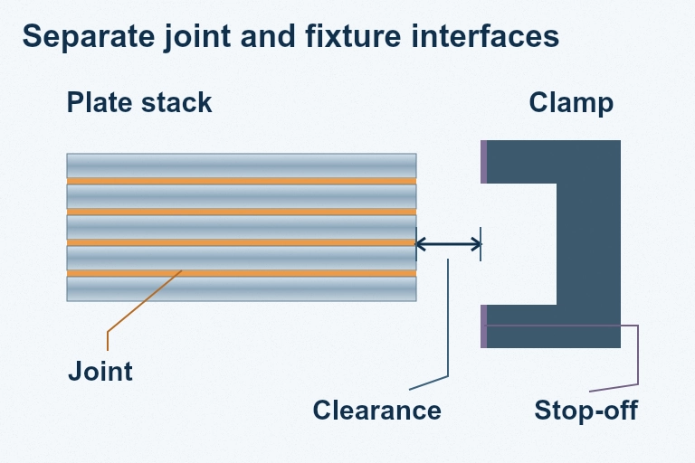
Examine fixture flatness, wear, accumulated deposits, loose particles and contact surfaces after the approved cleaning step. A particle trapped under a thin base plate can produce a local mark, while a distorted support can alter stack alignment. Record these observations before replacing the fixture so the relationship to the failed units is not lost. Do not specify a universal clamp gap from an undimensioned photograph; the hot assembly and fixture design determine the clearance.
Where stop-off is part of the qualified method, verify its material compatibility, placement, condition and drying instructions. Manufacturer data for furnace-brazing stop-off explains that it restricts alloy flow where it is applied and that poor solvent removal can undermine its adhesion. Keep it out of the desired joint. More coating is not a substitute for a sound fixture, and a brand name or country of origin is not evidence that the application is controlled.
Separate damage caused during handling or fixture release from damage formed during heating. Check how the cooler was moved, supported and removed, and whether removal required abnormal force. If a cooler sticks to the fixture, pulling it free can add a second failure mechanism. Preserve the affected interface for examination and assess any resulting deformation or crack risk before allowing further processing.
Separate atmosphere faults from product-side contamination
Use the timing and distribution of discoloration to choose the next check. Compare pressure and temperature histories, gas transitions, cooling events and affected load positions. Look for differences between the cooler surface and furnace surfaces. The dedicated part-discoloration troubleshooting guide explains this process-phase approach in more detail. It is preferable to assuming that all dark parts need another brazing cycle.
Review the condition of load supports, nearby hot-zone components and chamber access before returning the equipment to production. Distinguish evidence of a leak, moisture, residue carried in with a fixture, and a pumping-system problem. Ipsen's diagnostic questionnaire likewise separates process records, hot-zone condition, maintenance changes and gas-system checks. The photograph below identifies work-zone surfaces; it does not show a faulty or contaminated furnace.

If oil contamination is suspected, inspect the relevant evidence and use the approved maintenance route; see oil-backstreaming diagnosis and release checks. A pressure display alone cannot identify the contaminant. Likewise, a cold leak test may not reproduce every hot operating condition. Define the test state, measurement method and acceptance requirement rather than copying a generic leak-rate number.
Do not prescribe a universal burn-off temperature, dry-ice method or solvent wash for an unknown hot zone. Cleaning compatibility depends on insulation, heating elements, seals, deposits and the furnace design. A cleaning process can remove contamination, but can also damage components or introduce new residues if it is not suitable. Use the equipment-specific procedure and verify its result before exposing another production batch.
Authorize rework from the joint requirement, not its colour
Before rework, establish what must be restored and what cannot be recovered. A small external handling mark, a displaced port, an unfilled internal joint and an eroded plate wall need different assessments. Review the available dimensional allowance, the state of the joint and the permitted repair method. Obtain the required engineering or customer authorization; do not quietly substitute a cosmetic touch-up for the specified acceptance result.
A second thermal cycle exposes the whole assembly again. Existing copper joints may move, further material interaction may occur, and the fixture and cooling response may differ after the first cycle. Adding filler can also introduce material where none was intended. A fixed temperature increase is therefore not a repair rule. Define the proposed changes and their risks using the second-cycle qualification framework.
Set the post-rework inspection plan before carrying out the work. Repeat the relevant leak, dimensional and joint checks under the approved conditions, including circuit-to-circuit integrity where required. Keep the original failed results as well as the new results. If the necessary function cannot be demonstrated, further rework is not automatically justified simply because the cooler now looks better. The responsible quality authority must make the documented disposition.
Release the furnace and the product on separate evidence
Equipment recovery and product acceptance are different records. After a confirmed furnace fault, record the repair, approved cleaning, checks of the affected measurement or utility system, and the evidence needed to return that furnace to its qualified operating state. A successful empty-chamber check can support equipment release without proving that the previously affected oil coolers are acceptable.
For the product, connect each unit or batch to the inspection result and approved disposition. For process restart, use a representative load or trial defined by the change and risk. Confirm that the relevant thermal, pressure, cooling and inspection evidence is consistent with the approved production window. Retain the original deviation and corrective-action record so a recurrence can be compared with facts rather than recollection.
When the investigation identifies a configuration limitation, review the appropriate vacuum brazing furnace systems. For stainless/copper batch work, discuss the High-Temperature Vacuum Brazing Furnace against the actual load, work-zone access, measurement, pumping, gas-cooling and data requirements. Maximum temperature alone does not resolve a recurring rejected-batch problem.
High-Temperature Vacuum Brazing Furnace
Assess the production load and fixture together with temperature measurement, loaded pressure response, gas transitions, cooling and traceable records. Include representative acceptance trials when discussing a new or changed configuration.
What to include in your enquiry
- Cooler materials, drawing, filler form and relevant acceptance requirements.
- Defect photographs, leak locations, dimensions and affected load positions.
- Fixture drawing or contact map and the original production-load arrangement.
- Temperature, pressure, gas, cooling and alarm records from affected and reference runs.
- Recent changes, maintenance findings and the permitted scope of any proposed rework.