Alumina-to-Kovar Vacuum Brazing: Active Filler, Stress and Hermeticity
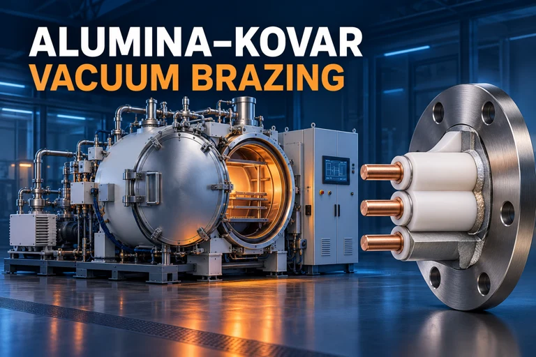
Reliable alumina-to-Kovar vacuum brazing starts with the interface architecture, not a copied furnace recipe. For 95% alumina joined to 4J33 Fe–Ni–Co sealing alloy, engineers normally compare direct active-metal brazing with an indirect metallized route. The choice must account for the actual ceramic grade, metal condition, filler, joint clearance, compliance, electrical duty and hermetic acceptance. Published cycles are useful experimental evidence, but they are not automatically transferable production settings.
Define the material pair and joint function first
“95% alumina” describes a family of ceramics rather than one invariant material. The balance can include glass-forming additives that influence surface chemistry, porosity, dielectric behavior and thermal expansion. Likewise, 4J33 is a Chinese Fe–Ni–Co controlled-expansion sealing alloy that is often described as Kovar-type, but its certified composition, heat treatment, plating condition and thermal-expansion curve should be verified for the purchased lot. Do not assume that data for another Kovar grade or a higher-purity alumina applies unchanged.
The joint function determines what “good” means. A vacuum electrical feedthrough may need a continuous hermetic boundary, stable insulation resistance, adequate conductor spacing and survival through repeated thermal cycles. A structural ceramic-to-metal attachment may prioritize shear capacity, alignment or fatigue instead. Record the service temperature, pressure differential, electrical voltage, atmosphere and allowable leak rate before selecting the brazing route.
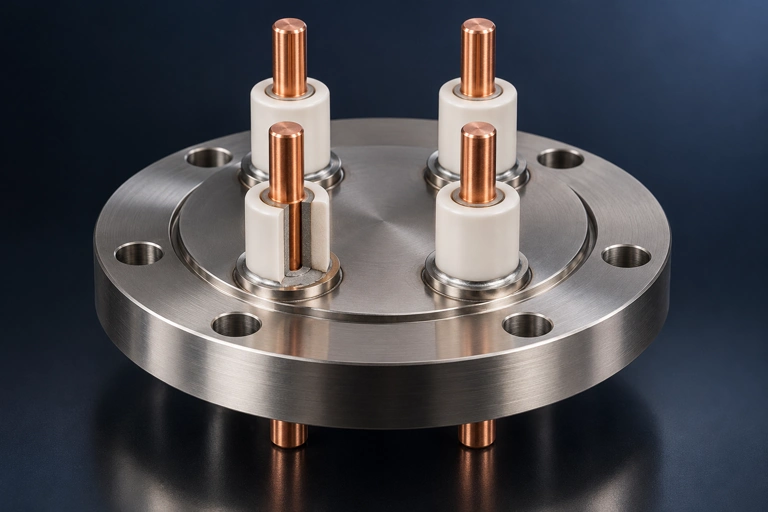
The assembly shown above is an original illustration of a common feedthrough concept, not a production drawing. Real designs need controlled ceramic wall thickness, generous edge radii, consistent annular clearance and a metal geometry that can accommodate differential movement. The flange, sleeve and conductor dimensions must be released together because changing one feature can change both filler flow and residual stress.
Choose between direct active brazing and a metallized route
Alumina is not readily wetted by many conventional silver-copper fillers. A direct route therefore uses an active element—commonly titanium in an Ag–Cu-based filler—to react at the ceramic surface and create an adherent interface. The benefit is a shorter process chain with no separate ceramic metallization. The trade-off is sensitivity to active-element availability, oxide condition, filler distribution and the thickness and continuity of reaction products.
An indirect route first creates a brazeable metallic layer on the ceramic, such as a qualified Mo–Mn metallization followed by a compatible surface finish. The metallized ceramic is then joined to the sealing alloy using a suitable filler. This adds operations and inspection points, but it can give the development team more control over the ceramic-side interface. A published comparison of 95% alumina and Kovar found the metallized route outperformed the tested direct route for that study’s exact materials and conditions; it does not establish a universal winner for every component.
| Route | Interface stack | Controls to qualify | Evidence required |
|---|---|---|---|
| Direct active brazing | Alumina / active reaction layer / filler / 4J33 | Ceramic condition, active filler placement, gap, oxygen exposure, liquid-phase time and cooling | Continuous wetting, controlled reaction layer, sections from critical locations, leak and electrical results |
| Metallized ceramic | Alumina / metallization / finish / filler / 4J33 | Metallization adhesion and coverage, finish thickness, storage condition, gap and cycle | Metallization acceptance, braze continuity, interfacial sections, leak and electrical results |
Manage thermal-expansion mismatch through geometry
A controlled-expansion alloy reduces the mismatch with alumina compared with many common structural metals, but it does not eliminate stress. The ceramic, alloy, braze layer and any metallization each respond differently while the assembly heats, cools and returns to service temperature. The highest local stresses often occur near free edges, abrupt thickness changes, sharp ceramic corners or rigid sections that prevent the metal from yielding.
Joint design should provide a controlled load path rather than relying on a thick filler deposit to absorb every mismatch. Practical measures may include thin metal sections, radial compliance, smooth transitions, adequate ceramic edge radii and a ductile filler or interlayer where compatible. The correct combination depends on the assembly geometry and service cycle. Finite-element analysis can compare concepts, but its material data and boundary conditions should be checked against representative coupons and full joints.
Fixtures also belong to the stress design. They must preserve alignment and the intended capillary gap without clamping the ceramic so rigidly that thermal movement creates cracks. Use ceramic-compatible support materials, minimize unnecessary contact area and confirm that fixture mass does not create a large temperature lag. Inspect distortion and cracks after the complete cooling schedule, not only immediately after filler melting.
Qualify the real filler, clearance and thermal window
There is no defensible universal temperature, pressure or hold-time recipe for every alumina-to-4J33 assembly. The active filler composition, metallization system, metal plating, component mass, joint gap, furnace gas load and temperature measurement method all change the usable window. Published values should therefore define experimental boundaries, not replace a procedure qualification.
Start with traceable material certificates and controlled coupons that reproduce the intended ceramic finish, metal preparation, filler form and joint clearance. Record cleaning, assembly time, fixture condition and filler mass. During the cycle, document vacuum behavior under load, ramp rates, load temperature—not only controller temperature—time above the relevant liquidus range and cooling rate through the stress-sensitive interval.
Microstructure is part of the process evidence. A 2014 study of Ti-metallized alumina brazed to Kovar showed that both the ceramic-side reaction layer and the residual filler thickness affected joint strength. That finding supports measuring layers and gap-related features in the qualified system. It does not provide a stand-alone drawing tolerance for a different filler, metallization process or production geometry.
Verify hermetic, electrical and mechanical performance together
A favorable helium leak result is essential for many feedthroughs, but it cannot describe the entire interface. Development inspection should combine an appropriately sensitive leak test with visual inspection, dimensional checks and metallographic sections. Sections should sample critical edges, filler-entry locations and areas where fixture contact or temperature lag is expected. Look for unfilled regions, ceramic cracking, excessive reaction products, porosity and erosion of thin metal features.
Electrical assemblies also need insulation-resistance and dielectric tests at conditions relevant to service. These tests must consider surface cleanliness, conductor spacing and ceramic geometry rather than attributing every failure to the braze alone. Structural qualification may add tensile, shear, proof-load or fatigue testing. Thermal cycling should reproduce the meaningful service range and dwell pattern, followed by repeat leak and electrical tests to reveal cracks that were not open after the first furnace cycle.
Acceptance criteria should be set before production. Link each finished part or batch to ceramic and metal lots, filler batch, metallization or plating records, cleaning status, fixture revision, load position, furnace recipe and inspection result. This traceability turns a one-time successful sample into a controllable manufacturing process.
Connect interface control to the furnace and load
The furnace must preserve the surface state established during preparation. Hot-zone material, fixture compatibility, pump-down performance, contamination history, temperature uniformity and sensor placement all influence the alumina–metal interface. An empty-chamber vacuum reading does not prove the same pressure behavior after ceramic, filler, binders, fixtures and a production load begin to outgas.

A clean, qualified work zone supports repeatable heating and cooling around the complete assembly. Load thermocouples or another justified temperature-verification method should represent the slowest and most critical locations. For larger parts, confirm that the selected vacuum brazing furnace system can accommodate fixture mass, temperature-uniformity needs, vacuum cleanliness and controlled cooling without creating excessive gradients.
Before scaling up, review the broader route-selection principles in High-Temperature Ceramic-to-Metal Joining. Then qualify the exact 95% alumina, 4J33, filler or metallization system and geometry described by the current drawing.

High-Temperature Vacuum Brazing Furnace
Configure the work zone, vacuum package, temperature measurement and controlled cooling around the ceramic–metal interface and acceptance plan.
- Graphite or molybdenum hot-zone routes for different material and cleanliness needs
- Work-zone and fixture planning for ceramic-to-metal feedthroughs and assemblies
- Cycle records tied to representative load verification and product acceptance
Prepare an alumina-to-Kovar brazing brief
For a focused furnace and process review, provide the alumina grade and drawing, 4J33 certificate and condition, direct-active or metallized route, filler designation and form, joint clearance, cleaning and plating records, fixture layout, representative load, service temperature, electrical duty, leak criterion and planned thermal cycling.
Discuss your ceramic-to-metal applicationTechnical references
- Microstructure and Properties of Al2O3 Ceramic and Kovar Alloy Joints Brazed Directly and Indirectly, Frontiers in Materials, 2020.
- Microstructure and mechanical properties of alumina/Kovar alloy joint brazed with Ag–5Pd filler metal, Ceramics International, 2014.
- Alleviating residual stress in ceramic-to-metal joints, TWI.
- Leak-Tight Ceramic-to-Metal Joints, EWI.