Carrier-based loading
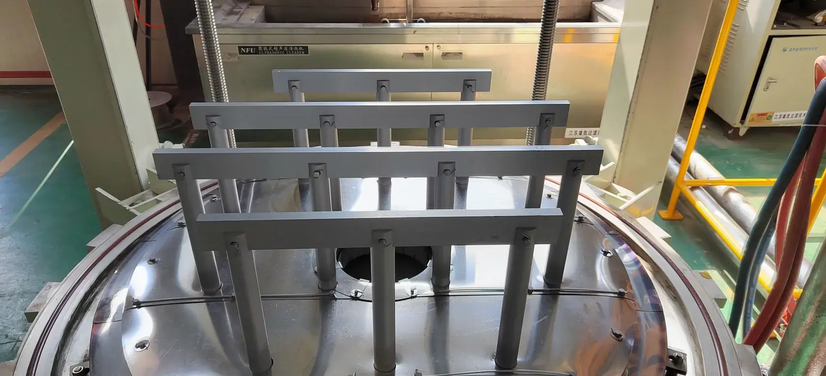
Parts, trays and tooling are assembled on the lower carrier before the complete load is raised into the chamber.
Stable load support
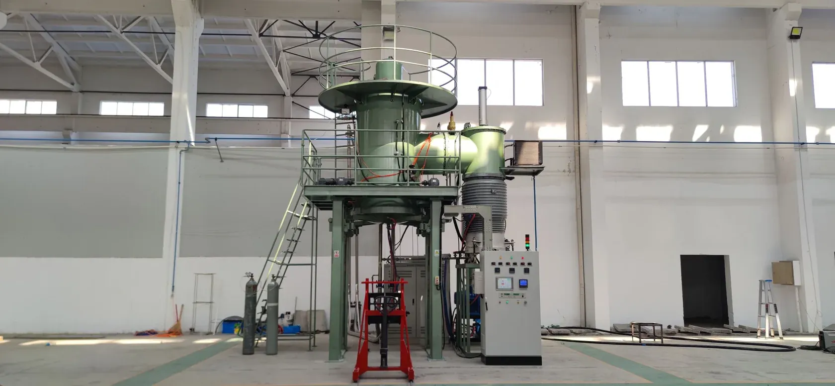
VTSL bottom-loading vacuum sintering platform
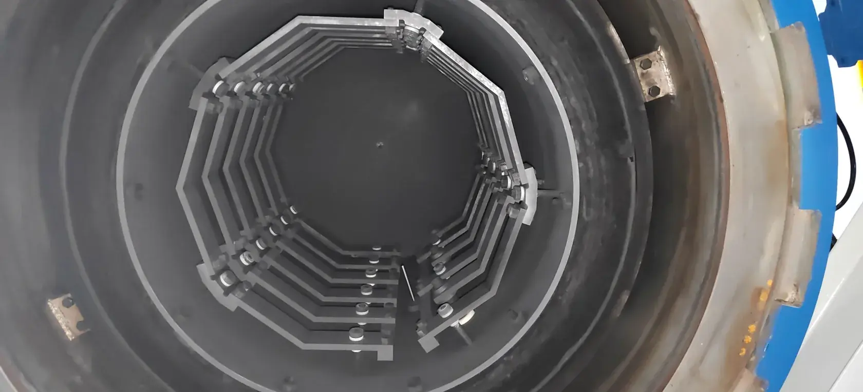
A vertical furnace platform for high-temperature vacuum sintering of compact, heavy or tall loads. The lower carrier, graphite hot zone, vacuum system and process controls are engineered as one integrated production system.
Process fit
Vertical bottom loading provides open access for fixture preparation and supports controlled movement of the complete load into the hot zone. The architecture is well suited to heavy, tall and fixture-intensive parts.
Parts, trays and tooling are assembled on the lower carrier before the complete load is raised into the chamber.
Stable load supportEvacuation, programmed heating, dwell, optional argon backfill and cooling operate as a coordinated recipe.
Vacuum + argonThe working zone, graphite hot zone, pump train, lifting system and controls are matched to the production requirement.
Engineered configurationVTSL reference configurations
Use these VTSL configurations as a technical starting point. Working-zone dimensions, load capacity, temperature class, vacuum system, gas-pressure capability, carrier arrangement and controls can be customized around the material and production cycle.
| Reference configuration | System area | Technical values |
|---|---|---|
| VTSL-120 | Working zone and load | Ø350 × H400 mm uniform zone; ≤200 kg load including tray |
| VTSL-120 | Temperature | 1,800 °C maximum; ≤1,650 °C high-temperature operation with tungsten-rhenium thermocouple control |
| VTSL-120 | Vacuum performance | 7.9 × 10⁻⁵ Pa ultimate vacuum; 4.8 × 10⁻³ Pa working vacuum at 1,650 °C in an empty furnace; 0.08 Pa/h pressure-rise rate |
| VTSL-120 | Thermal performance | +2.7 / -2.6 °C uniformity at 1,000 °C using a 9-point test; 3–10 °C/min heating rate; 100 mm insulation; 45% hold output at 1,650 °C |
| VTSL-120 | Power and atmosphere | 150 kW / 380 V heating power and voltage; argon backfill up to 0.8 bar |
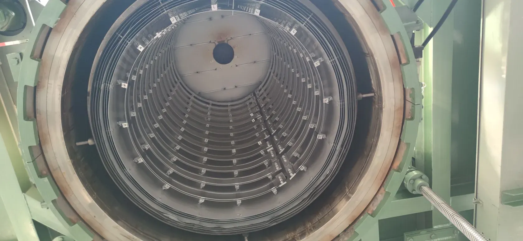
| VTSL-120 | Hot zone and structure | Graphite resistance heating with composite soft- and hard-graphite-felt insulation; single-chamber vertical bottom loading for vacuum and argon-protected processing |
| VTSL-8012 | Production configuration | Ø800 × H1,200 mm uniform zone; 1,350 °C use temperature; 1,500 kg load including tooling |
| Large VTSL | Large-scale configuration | Ø2.3 m × H1.4 m working space; 2,000 °C working temperature; 12 bar gas-pressure capability |
| Custom VTSL | Engineered configuration | Other working-zone dimensions, load capacities, temperature classes, vacuum systems, gas-pressure levels, carrier layouts, control packages and utility interfaces can be developed for the required production process. |
System architecture
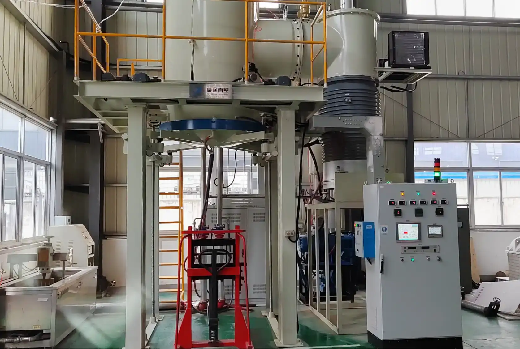
The carrier, lift structure, chamber, graphite hot zone, vacuum hardware and controls operate as a coordinated installation for repeatable production cycles.
Materials and process value
VTSL configurations support graphite and carbon products, technical ceramics, refractory materials and powder-metallurgy components that benefit from stable fixture support, high vacuum and programmable thermal control.
Graphite products and carbon-based components requiring a clean high-temperature cycle and a load-specific hot-zone arrangement.
Ceramic loads where setter design, shrinkage behavior, packing density and temperature uniformity affect the sintering result.
Powder-metallurgy parts and refractory materials requiring controlled vacuum, dwell and cooling conditions.
Typical operating sequence
The lower carrier keeps load preparation separate from the sealed thermal cycle and supports a clear, repeatable operating sequence.
Confirm the material, part envelope, tooling and total load mass.
Arrange the parts, trays and fixtures on the lower work carrier.
Lift the carrier into position and complete the chamber-closing sequence.
Run the programmed pumping, heating and dwell stages.
Complete the controlled cooling and optional gas-backfill sequence.
Return the carrier for inspection and safe part handling.
Delivery and support
FAQ
VTSL is a vertical bottom-loading vacuum furnace platform for high-temperature sintering and controlled thermal processing. The complete load is prepared on the lower carrier and raised into the chamber for evacuation, heating, holding and cooling.
VTSL-120 provides a 350 mm diameter by 400 mm high uniform zone, 1,800 °C maximum temperature, 7.9 × 10⁻⁵ Pa ultimate vacuum, 4.8 × 10⁻³ Pa working vacuum at 1,650 °C in an empty furnace, and a 0.08 Pa/h pressure-rise rate.
Yes. VTSL configurations include an 800 mm diameter by 1,200 mm high sintering zone with a 1,500 kg load capacity, as well as a large system with a 2.3 m diameter by 1.4 m high working space, 2,000 °C working temperature and 12 bar gas-pressure capability.
Provide the material, part and fixture dimensions, total load mass, target thermal cycle, vacuum or argon requirement, throughput, utilities and site layout. The engineering team will use these inputs to define the working zone, hot zone, carrier, vacuum system and control package.
Related sintering routes
Sintering system familyCompare furnace architectures for high-temperature densification under controlled vacuum and atmosphere.
Flexible sintering platformFor varied material systems, controlled-atmosphere cycles and optional integrated process steps.
Material applicationReview high-temperature routes for demanding technical-ceramic materials and components.
Industry applicationExplore vacuum processing for powder metals, refractory alloys and high-value metallurgical parts.
Process knowledgeUnderstand densification, dimensional control and process variables for powder-based parts.
Pressure-assisted alternativeConsider axial force when pressure-assisted densification is technically required.
Technical consultationSend the material, fixture, total load mass and target thermal cycle for an engineering review.
Configure your VTSL system
Share the part, material, fixture, cycle and utility information. The technical team will define the working zone, hot zone, vacuum train, carrier and service scope.